Multi-station transfer mechanism and motor bearing assembly equipment

A load-shifting and displacement technology, which is applied in the direction of electromechanical devices, metal processing equipment, assembly machines, etc., can solve the problems of reducing the service life of motors, poor assembly compatibility of different types of products, and difficulty in meeting flexible production.

Active Publication Date: 2020-06-19
BOZHON PRECISION IND TECH CO LTD
View PDF16 Cites 12 Cited by
  • Summary
  • Abstract
  • Description
  • Claims
  • Application Information

AI Technical Summary

Problems solved by technology

If the new energy motor is assembled manually, there are many problems
Taking the assembly of the rotor assembly as an example, the rotor and bearing are easy to be damaged during the assembly operation after shrinking the bearing. When installing the circlip, the circlip cannot be assembled in place at one time and the circlip has a large locking force and scratches the rotor shaft. surface, it is easy to cause seal failure and reduce the service life of the motor
[0003] Although the semi-automatic or automatic operation of rotor assembly assembly has been realized at present, these semi-automatic or automatic operation equipment are generally large in size, and the assembly compatibility for different types of products is poor, and it is difficult to meet the needs of flexible production

Method used


Image

  • Multi-station transfer mechanism and motor bearing assembly equipment
  • Multi-station transfer mechanism and motor bearing assembly equipment
  • Multi-station transfer mechanism and motor bearing assembly equipment

Examples


Embodiment 1

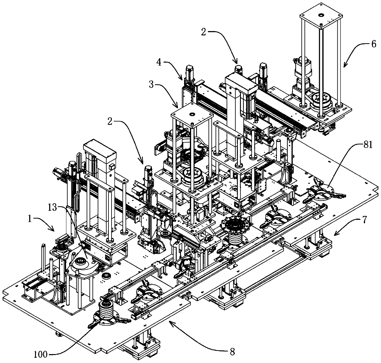
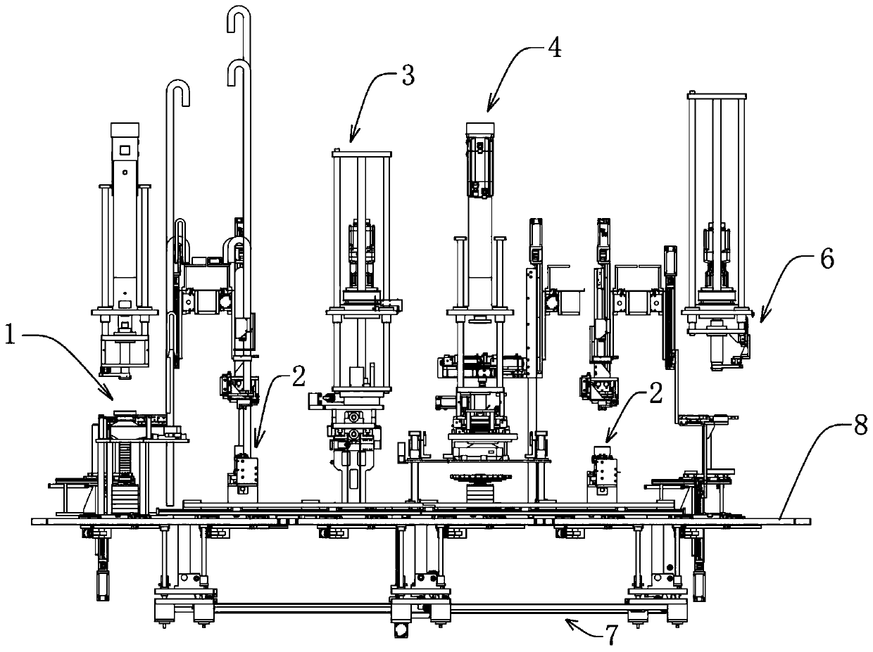
[0068] Such as Figure 1a with Figure 1b As shown, this embodiment relates to a motor bearing assembly equipment, including the first station-bearing assembly mechanism 1, the second station-circlip assembly mechanism 2, the third station-overturn mechanism 3, the fourth station, etc. Station-end cover bearing assembly mechanism 4, fifth station-circlip assembly mechanism 2, sixth station-sealing ring assembly mechanism 6, six-station loading mechanism 7 and workbench 8.

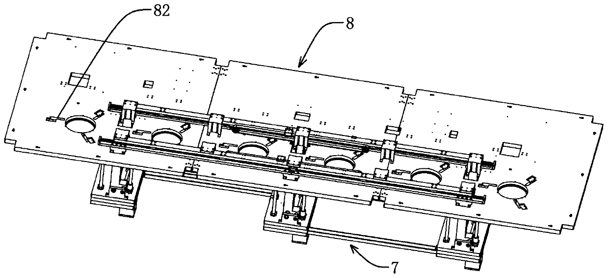
[0069] Such as figure 2 , Figure 3a , Figure 3b with Figure 3c As shown, the six-station load displacement mechanism 7 includes: an X-axis transfer assembly 71, a Y-axis spacing adjustment assembly 72, and three sets of Z-axis lifting assemblies 73. The three sets of Z-axis lifting assemblies 73 are divided into a middle group and two outer groups.

[0070] Each group of Z-axis lifting assemblies 73 includes a lifting platform 733 and two groups of ball screws 731 vertically arranged on the lifting ...


PUM


Abstract

The invention discloses a multi-station transfer mechanism and motor bearing assembly equipment, and belongs to the technical field of motor assembly. The multi-station transfer mechanism comprises anX-axis transfer assembly, a Y-axis spacing regulating assembly and at least one group of Z-axis lifting assemblies; each Z-axis lifting assembly comprises a rolling ball lead screw and a lifting table which is fixedly connected to a nut in the rolling ball lead screw, wherein the upper end of the lead screw in the rolling ball lead screw is provided with an operation table, the lower end of the lead screw in the rolling ball lead screw is arranged on a support base in a penetrating mode, and the lower end of the lead screw is in transmission connection to a drive motor; the Y-axis spacing regulating assembly comprises two groups of supporting plates which are separately and fixedly connected onto supporting frames in a one-to-one correspondence mode; the supporting frames are arranged ona two-way lead screw in pair, and the two-way lead screw is in transmission connection to a drive motor; and the X-axis transfer assembly comprises transfer plates which axially extend along the X-axis, and are provided with clamping assemblies, and the transfer plates are axially arranged on the supporting plates slidably in the one-to-one correspondence mode. The multi-station transfer mechanismcan quickly take workpieces and switches to different stations, so that operation on each station is convenient.

Description

technical field [0001] The invention relates to a technology in the field of motor assembly, in particular to a multi-station loading mechanism and motor bearing assembly equipment. Background technique [0002] With the development of new energy vehicles, the demand for new energy motors is increasing. If the new energy motor is assembled manually, there are many problems. Taking the assembly of the rotor assembly as an example, the rotor and bearing are easy to be damaged during the assembly operation after shrinking the bearing. When installing the circlip, the circlip cannot be assembled in place at one time and the circlip has a large locking force and scratches the rotor shaft. surface, it is easy to cause seal failure and reduce the service life of the motor. [0003] Although the semi-automatic or automatic operation of rotor assembly assembly has been realized at present, these semi-automatic or automatic operation equipment are generally large in size and have po...

Claims


Application Information

Patent Timeline
Patent Type & Authority Applications(China)
IPC IPC(8): B23P21/00B23P11/02H02K15/00
CPCB23P11/025B23P19/001B23P19/007B23P21/004H02K15/00
Inventor 姚江平鄢飞盛绍雄
Owner BOZHON PRECISION IND TECH CO LTD
Why Eureka
Try Eureka