Book packaging mechanism based on annular paper packaging
A book and ring paper technology, which is applied in packaging, transportation packaging, transportation and packaging, etc., can solve the problems of poor packaging quality, low degree of automation and low efficiency of book packaging machines, and achieve low manufacturing costs, economical and easy assembly, The overall structural integrity of the effect
- Summary
- Abstract
- Description
- Claims
- Application Information
AI Technical Summary
Problems solved by technology
Method used
Image

Examples
Embodiment 1
[0026] Embodiment 1 A book packaging mechanism based on ring paper packaging according to the present invention includes:
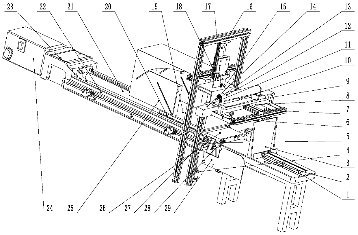
[0027] The vertical board pushing mechanism comprises a vertical board support part and a vertical board pushing part, and the top of the vertical board support part is provided with a conveying table 2 for placing books; the vertical board pushing part is arranged on the conveying table of the vertical board supporting part 2, and the pushing end of the vertical plate pushing part is aligned with the ball screw guide transport mechanism, which is used to push the books to the packing table of the ball screw guide transport mechanism;
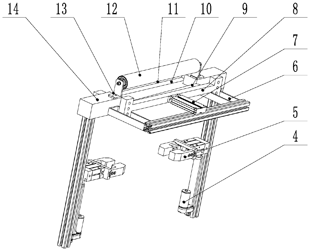
[0028] The paper feeding mechanism is arranged between the vertical plate pushing mechanism and the packing workbench, including a vertical support part, a wrapping paper conveying part, a cutting part and a wrapping paper clamping part, and the wrapping paper conveying part is erected on the top of the supporting frame, I...
Embodiment 2
[0041] Embodiment 2 A book packaging mechanism based on ring paper packaging according to the present invention includes a vertical plate pushing mechanism, a paper feeding mechanism, a ball screw guide rail transportation mechanism, and a paper packaging mechanism;
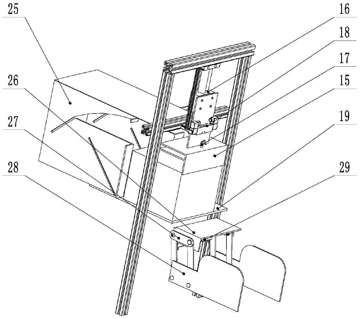
[0042] The vertical plate pushing mechanism comprises a vertical plate push rod cylinder 1, a conveying platform 2 and a vertical plate 3. The vertical plate push rod cylinder 1 of the executive mechanism of the vertical plate pushing mechanism is a two-rod cylinder, and the two-rod cylinder drives the vertical plate to push the book to the packing workbench; the vertical plate push rod cylinder 1 is fixed on the surface of the conveying table 2 , the vertical board push rod cylinder 1 is connected to the vertical board 3, and the vertical board 3 is used to push the books to the packing workbench 19.
[0043] The paper feeding mechanism includes an electric push rod 4, a pneumatic clamp 5, a two-rod cylinder 7, ...
Embodiment 3
[0049] Embodiment 3 The difference between this embodiment and Embodiment 2 is that: the parallel four-bar linkage mechanism is surrounded by four rod bodies hinged from end to end, which are respectively upper rod, lower rod, front rod and rear rod, Among them, the lower folding board and the side folding board are installed on the upper pole and the lower rod respectively, and the parallel four-bar linkage mechanism is connected with the movable end of the steering gear. Through the movement of the steering gear, the lower folding board and the side folding board are driven to perform corresponding folding actions. .
PUM
 Abstract
Description
Claims
Application Information