Flexible peak regulation system and method for air energy storage of power plant

An air energy storage and flexible technology, applied in the direction of machines/engines, steam engine devices, liquid variable displacement machinery, etc., can solve problems such as energy waste, compressor performance deterioration, and lack of compressors

Pending Publication Date: 2020-06-19
XIAN XIRE ENERGY SAVING TECH +1
View PDF0 Cites 22 Cited by
  • Summary
  • Abstract
  • Description
  • Claims
  • Application Information

AI Technical Summary

Problems solved by technology

[0004] In the liquid compressed air energy storage system, a large amount of compression heat will be generated in the process of compressing the air. In order to improve the energy storage efficiency of the energy storage system, a heat storage system will be built to recover the compression heat and improve the temperature grade of the compression heat as much as possible. At present In the compressed air energy storage technology, the pressure of the outlet air of the last stage compressor is about 10MPa, and the temperature is basically 200°C to 400°C. There is still a trend of further improvement at present, but increasing the operating temperature of the compressor will lead to deterioration of the compressor performance and power consumption. The capacity increases and the service life decreases. At present, there is no compressor that can withstand this level of temperature and pressure on the market.
In addition, for conventional liquid compressed air energy storage systems, the heat obtained by the heat storage system during the energy storage process is greater than the heat required during the energy release process, which will cause energy waste

Method used


Image

  • Flexible peak regulation system and method for air energy storage of power plant
  • Flexible peak regulation system and method for air energy storage of power plant

Examples


Embodiment Construction

[0031] The patent of the present invention will be described in further detail below in conjunction with the accompanying drawings and specific embodiments. The specific embodiments described here are only used to explain the present invention, and are not intended to limit the present invention.

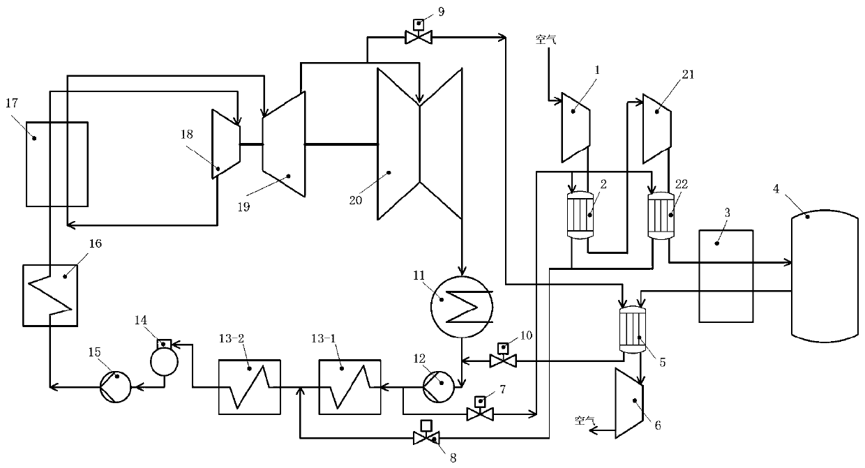
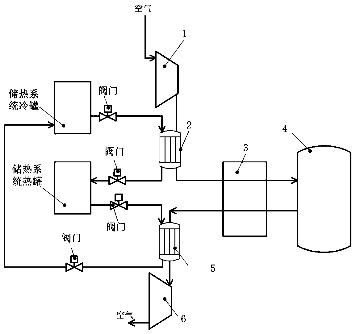
[0032] Such as figure 1As shown, a power plant air energy storage flexible peaking system of the present invention includes: a compressor 1, a cooler 2, a gas-liquid conversion device 3, a liquid air storage tank 4, a heater 5, an expander 6, a new A liquid compressed air energy storage system composed of a compressor 21 and a new cooler 22; it consists of a condenser 11, a condensate pump 12, a first-stage low-pressure heater 13-1, a second-stage low-pressure heater 13-2, and a deaerator 14. Coal-fired power generation system composed of feed water pump 15, high-pressure heater 16, boiler 17, high-pressure cylinder 18, medium-pressure cylinder 19 and low-pressure cylinder 20; first...


PUM


Abstract

The invention discloses a flexible peak regulation system and method for air energy storage of a power plant. The system comprises a liquid compressed air energy storage system and a coal-fired unit power generation system. The operation modes of the system comprise an energy storage mode and an energy release mode. The energy storage mode is started when the power utilization load of a power gridis low and residual electric energy exists, and the residual electric energy is used for driving a multi-stage compressor to compress air. The energy release mode is started when the power utilization peak of the power grid is short of electric energy supply, and low-temperature air is heated by utilizing steam extraction of a coal-fired unit to push an expansion machine to generate power and output electric energy to the outside. According to the invention, the efficiency of the energy storage system can be improved, and meanwhile, the problems of high energy consumption, short service lifeand the like when a high-pressure compressor is used are avoided; according to the invention, a heat storage system in a traditional liquid compressed air energy storage system is omitted, the investment of the energy storage system is reduced, and meanwhile, the problem of mismatching of heat in the energy storage process and the energy release process is solved.

Description

technical field [0001] The invention belongs to the technical field of energy storage peak regulation, and specifically relates to a power plant air energy storage flexible peak regulation system and method, which is applicable to various thermal power plants with coal-fired units as typical, and can improve the flexibility of coal-fired units , peak shaving capability and economic benefits, and at the same time can improve the energy storage efficiency of the liquid compressed air energy storage system. Background technique [0002] my country's wind energy, solar energy and other renewable energy are developing rapidly year by year. By the end of 2018, my country's photovoltaic and wind power installed capacity reached 172 million kilowatts and 184 million kilowatts respectively, and the total annual power generation reached 543.5 billion kilowatt-hours. , The shortcomings of strong randomness, in order to fully absorb new energy, the power grid has greatly increased the re...

Claims


Application Information

Patent Timeline
Patent Type & Authority Applications(China)
IPC IPC(8): F01K11/00F01K7/02F01K3/18F01K13/00F04B41/02F04B41/06F04B39/06
CPCF01K3/18F01K7/02F01K11/00F01K13/00F04B39/06F04B41/02F04B41/06Y02E60/16
Inventor 居文平张建元马汀山常东锋范庆伟黄嘉驷许朋江谢天
Owner XIAN XIRE ENERGY SAVING TECH
Why Eureka
Try Eureka