
Conveying chain

A technology for conveying chains and inner chain plates, applied in the field of mechanical transmission, can solve the problems of easy deformation of chain plates, grinding chain plates, chain failure, etc., and achieve the effects of ensuring strength, reducing thermal deformation, and small temperature changes

Pending Publication Date: 2020-06-19
ANHUI HUANGSHAN HENGJIU CHAIN TRANSMISSION CO LTD
View PDF0 Cites 1 Cited by
  • Summary
  • Abstract
  • Description
  • Claims
  • Application Information

AI Technical Summary

Problems solved by technology

During the use of the chain of the cooling bed machine, due to the high temperature of the conveyed section steel, the heat is directly transmitted to the chain. The chain enters the cooling bed from the section steel to the cooling bed, and the temperature ranges from 600°C to normal temperature. Due to thermal expansion and contraction, the cooling of the parison drives the chain to move sideways during operation, and the channel is laterally squeezed, resulting in wear
Due to the hardness problem of the guide plate and the friction with the guide rail, the guide plate is excessively worn and the chain plate is worn out, causing the chain to fail

Method used


Image

  • Conveying chain
  • Conveying chain
  • Conveying chain

Examples


Embodiment 1

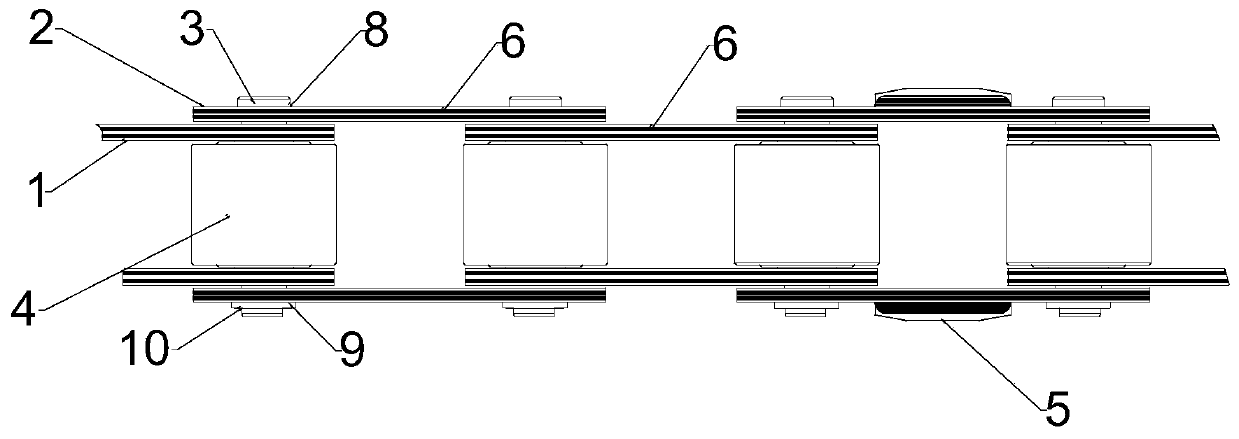
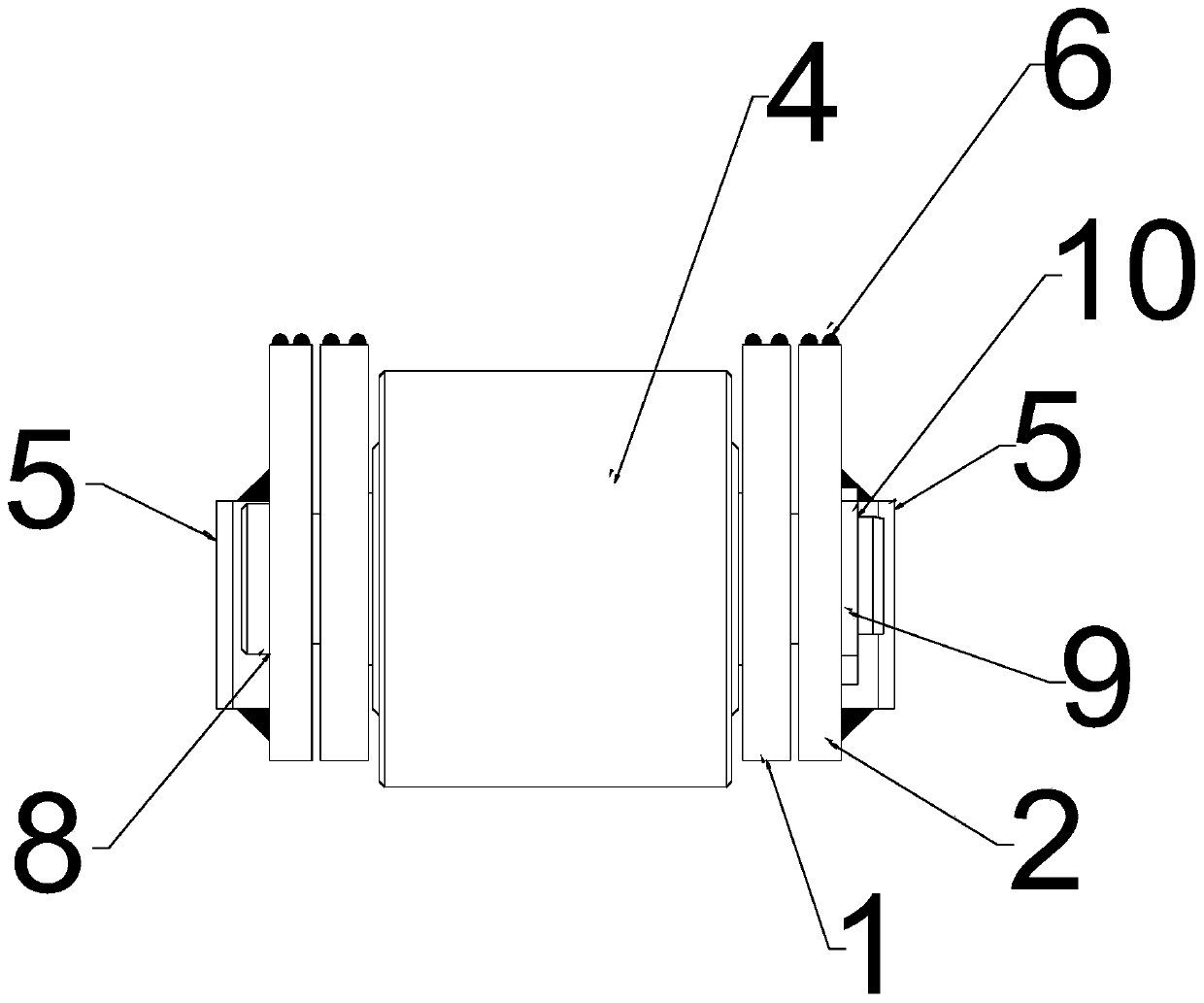
[0020] see Figure 1-Figure 4 , a conveyor chain, including an inner chain plate 1, an outer chain plate 2, a pin shaft 3 and a sleeve 4, and the pin shaft 3 passes through the outer chain plate 2 on the rear side and the inner chain plate on the rear side in sequence from back to front. The chain plate 1, the sleeve 4, the inner chain plate 1 on the front side and the outer chain plate 2 on the front side; the outer chain plate 2 is welded and fixed with the high The hardness guide plate 5; the upper edge of the inner chain plate 1 and the outer chain plate 2 is welded with a welding layer 6, which has the technical effect of high temperature resistance and wear resistance, and can reduce the heat transfer of high temperature section steel to the chain plate; The inner chain plate 1 and the outer chain plate 2 are provided with a heat dissipation window 7, and the heat dissipation window 7 is round, rectangular or waist-shaped; the heat dissipation window 7 is a through hole ...


PUM

PropertyMeasurementUnit
Hardnessaaaaaaaaaa

Abstract

The invention relates to the technical field of mechanical transmission, and specifically relates to a conveying chain. The conveying chain comprises inner chain plates, outer chain plates, a pin shaft and a sleeve, wherein the pin shaft sequentially penetrates through the outer chain plate at a rear side, the inner chain plate at the rear side, the sleeve, the inner chain plate at a front side and the outer chain plate at the front side from the rear to the front; a high-hardness guide plate is welded and fixed to a side end surface away from the corresponding inner chain plate, of each outerchain plate; and welding layers are welded to the upper edges of each inner chain plate and the corresponding outer chain plate, heat dissipation windows are formed in each inner chain plate and thecorresponding outer chain plate, a step surface is machined at a rear end of the pin shaft, a retainer ring groove is machined in a front end of the pin shaft, and a locking retainer ring is installedin the retainer ring groove in a clamping manner. According to the conveying chain, the wear and the deformation of the chain plates is greatly reduced, and meanwhile, the service lives of the guideplate and the chain are effectively prolonged; and the conveying chain is worthy of being popularized and used.

Description

technical field [0001] The invention relates to the technical field of mechanical transmission, in particular to a conveying chain. Background technique [0002] Chains are generally metal links or rings, which are mostly used for mechanical transmission and traction. During the use of the chain of the cooling bed machine, due to the high temperature of the conveyed section steel, the heat is directly transmitted to the chain. The temperature of the chain is from 600°C to normal temperature when the steel section enters the cooling bed and then leaves the cooling bed. Due to thermal expansion and contraction, the cooling of the parison drives the chain to move sideways during operation, and the channel is laterally squeezed, causing wear. Due to the hardness problem of the guide plate and the friction of the guide rail, the guide plate is excessively worn and then the chain plate is worn and the chain fails. Therefore, the problems that need to be solved urgently for the c...

Claims


Application Information

Patent Timeline
IPC IPC(8): F16G13/06F16G15/12
CPCF16G13/06F16G15/12
Inventor 张可飞周健周子棠
Owner ANHUI HUANGSHAN HENGJIU CHAIN TRANSMISSION CO LTD
Learn More