
Ball valve and processing equipment thereof

A technology for processing equipment and ball valves, which is applied in the field of ball valves and their processing equipment, can solve the problems of inconvenient grinding at the same time, high grinding intensity, and easy slippage between the spherical edge and the sealing surface, and achieve the effect of improving the grinding efficiency and sealing performance

Pending Publication Date: 2020-06-19
VALVE BIWEI VALVE CO LTD
View PDF0 Cites 10 Cited by
  • Summary
  • Abstract
  • Description
  • Claims
  • Application Information

AI Technical Summary

Problems solved by technology

[0003] The grinding method of the ball is manual grinding (generally, the surface of the ball to be grinded is firstly repaired with a file and sandpaper, and then the ball and the valve seat are manually ground with a suitable grinding sand). However, manual grinding and mechanical grinding are only suitable for surface hardness0.1mm, the existing ball valve ball, in the process of use, after rotating a certain angle, the spherical surface of the ball contacts with the sealing surface at the channel to achieve the sealing effect, but the spherical surface is a smooth surface, and the edge of the sealing surface and the smooth spherical surface contact each other. Due to its own smoothness, the edge of the spherical surface and the sealing surface are easy to slip off. At the same time, it is not convenient to simultaneously polish the surface of the ball valve and the channel inside the ball when grinding the ball valve. The grinding intensity is high. Therefore, we propose a ball valve and its Processing Equipment

Method used


Image

  • Ball valve and processing equipment thereof
  • Ball valve and processing equipment thereof
  • Ball valve and processing equipment thereof

Examples


Embodiment approach

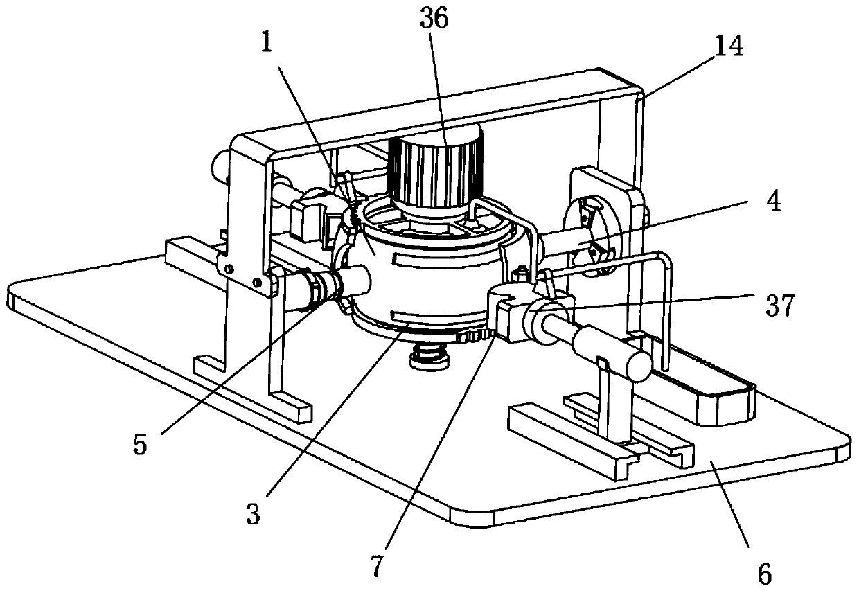
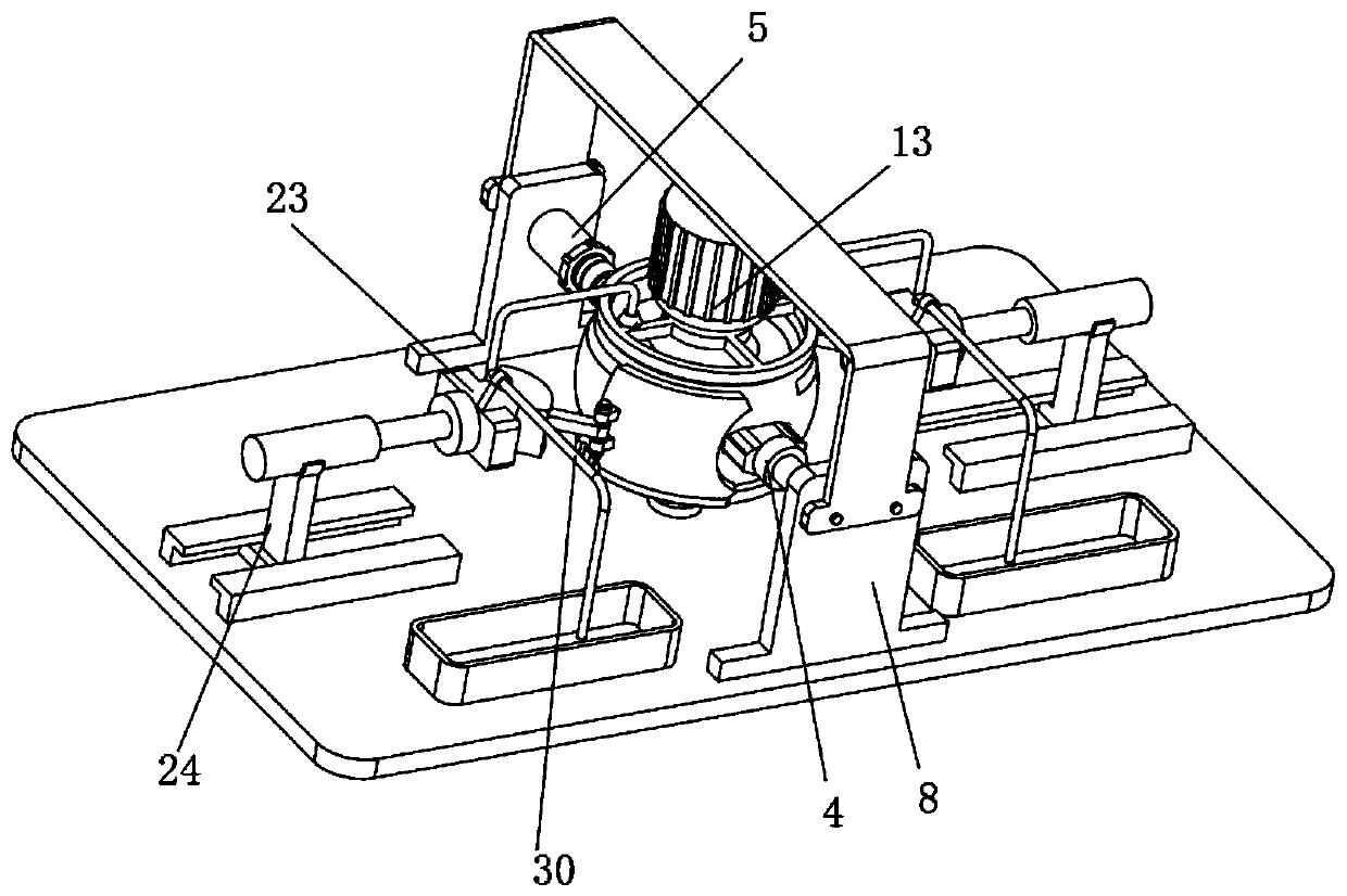
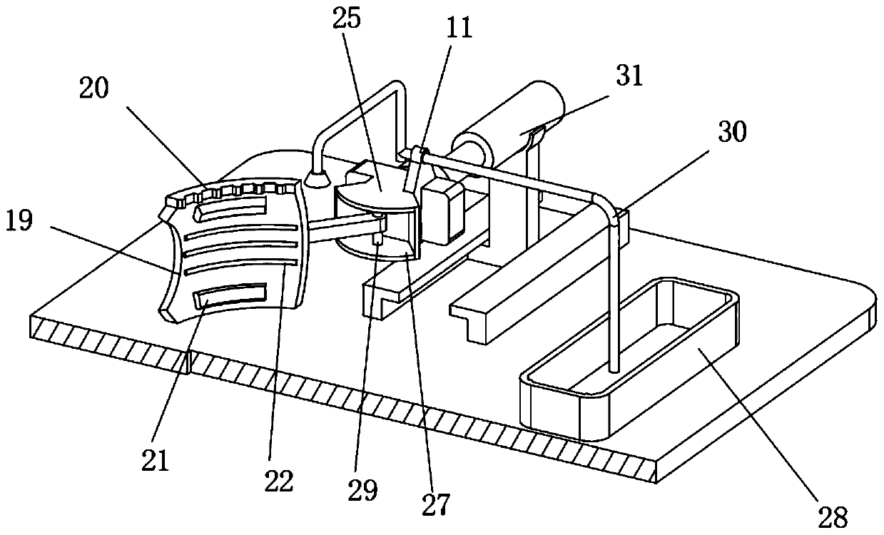
[0031] Specific implementation method: when the ball valve ball 1 is polished, after the ball valve ball 1 is installed on the workbench 6, by starting the cylinder 31, since the bottom of the cylinder 31 is socketed inside the chute 33 through the support seat 32, it can be adjusted according to the ball valve ball. 1. The diameter adjusts the position of the cylinder 31. Under the output power of the cylinder 31, the push plate 25 moves forward. At the same time, the push plate 25 is connected to the connecting plate 35 through the rotating shaft 29, and the connecting plate 35 is in contact with the contact plate 19. Because the contact plate 19 is a spherical arc surface, which is convenient to contact with the outside of the ball valve ball 1. When the friction groove bar 21 on the inner side of the contact plate 19 contacts with the sealing groove 3, the movement of the cylinder 31 is stopped. At this time, the grinding bar 22 on the contact plate 19 and The outer sides o...


PUM


Abstract

The invention discloses a ball valve and processing equipment thereof. The ball valve comprises a ball valve ball body, a channel is arranged in the ball valve ball body, two sealing clamping groovesare symmetrically formed in the outer side of the ball valve ball body, a valve rod is connected to one end of the ball valve ball body, a rotary rod is connected to the other end of the ball valve ball body, a working table for placing is arranged at the bottom of the ball valve ball body, the rotary rod and the valve rod are correspondingly connected with the two sides of the working table, anda polishing piece used for polishing the ball valve ball body is connected to the working table. The two sealing clamping grooves are formed in the outer side of the ball valve ball body, and the sealing of the ball valve ball body and a ball valve body during sealing is helped to be improved; meanwhile, when the ball valve ball body is produced, a radial piece and an axial piece correspondingly arranged in the polishing piece simultaneously polish the ball valve ball body, and the polishing processing efficiency during ball valve ball body production is conveniently improved; and meanwhile, when the ball valve ball body is polished, a spraying piece performs cooling processing on the surface of the ball valve ball body and the polishing piece, and the protection of the ball valve ball body and the polishing piece is facilitated.

Description

technical field [0001] The invention relates to the technical field of ball valve processing equipment, in particular to a ball valve and its processing equipment. Background technique [0002] Ball valve, the opening and closing part (ball) is driven by the valve stem and rotates around the ball valve axis. It can also be used for fluid adjustment and control. Among them, the hard-sealed V-type ball valve has a V-type ball core and surfacing welding. There is a strong shear force between the hard alloy metal valve seats, which is especially suitable for media containing fibers, tiny solid particles, etc., and the multi-way ball valve can not only flexibly control the confluence, diversion, and flow direction of the media on the pipeline At the same time, any channel can be closed to connect the other two channels. The ball and seat of the ball valve need to be ground after hardening. [0003] The grinding method of the ball is manual grinding (generally, the surface of the...

Claims


Application Information

Patent Timeline
Patent Type & Authority Applications(China)
IPC IPC(8): F16K5/06F16K5/08B24B11/02B24B15/04B24B41/06B24B27/00B24B55/02
CPCB24B11/02B24B15/04B24B27/0076B24B41/06B24B55/02F16K5/0605F16K5/0684F16K5/08
Inventor 方敏梅响林温华按周如星
Owner VALVE BIWEI VALVE CO LTD
Learn More