
Temperature sensing device and ring main unit temperature monitoring system

A technology of sensing devices and monitoring systems, applied in thermometers, measuring devices, electrical devices, etc., can solve problems such as cable measurement, burning, and large difference between temperature and cable internal temperature, and achieve the effect of reducing the probability of damage

Pending Publication Date: 2020-06-19
HANGZHOU ELECTRIC EQUIP MFG +2
View PDF1 Cites 1 Cited by
  • Summary
  • Abstract
  • Description
  • Claims
  • Application Information

AI Technical Summary

Problems solved by technology

[0005] After the ring network cabinet has been in operation for a long time, it is difficult to block the radiation of sunlight, and there is an over-sealed condition inside the ring network cabinet, which will affect the heat dissipation effect of the ring network cabinet equipment, causing heat accumulation inside the machine and temperature rise. high conditions, eventually damaging electrical equipment
In the case of large temperature changes, if the current humidity is high, even if the staff installed the infrared thermometer in the ring network cabinet in advance to monitor the internal temperature of the ring network cabinet, it is difficult to monitor the temperature of the outer layer of the cable in real time and effectively The measurement results in a large difference between the measured temperature and the internal temperature of the cable, which affects the effectiveness of temperature monitoring in the ring network cabinet; at the same time, even if a device for controlling temperature and humidity is used, it will also appear in the ring network cabinet equipment. In the case of condensation, some equipment will be damp and cause flashover or ladder accidents, and more serious accidents will cause burns and other accidents, which need to be improved

Method used


Image

  • Temperature sensing device and ring main unit temperature monitoring system
  • Temperature sensing device and ring main unit temperature monitoring system
  • Temperature sensing device and ring main unit temperature monitoring system

Examples


Embodiment Construction

[0026] The technical solutions in the embodiments of the present application will be clearly and completely described below in conjunction with the accompanying drawings in the embodiments of the present application. Obviously, the described embodiments are only some of the embodiments of the present application, not all of them. Based on the embodiments in this application, all other embodiments obtained by persons of ordinary skill in the art without making creative efforts belong to the scope of protection of this application.

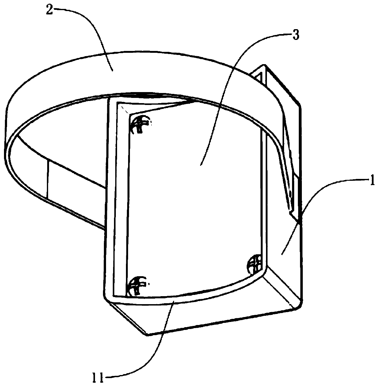
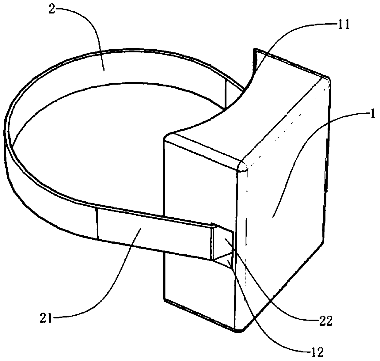
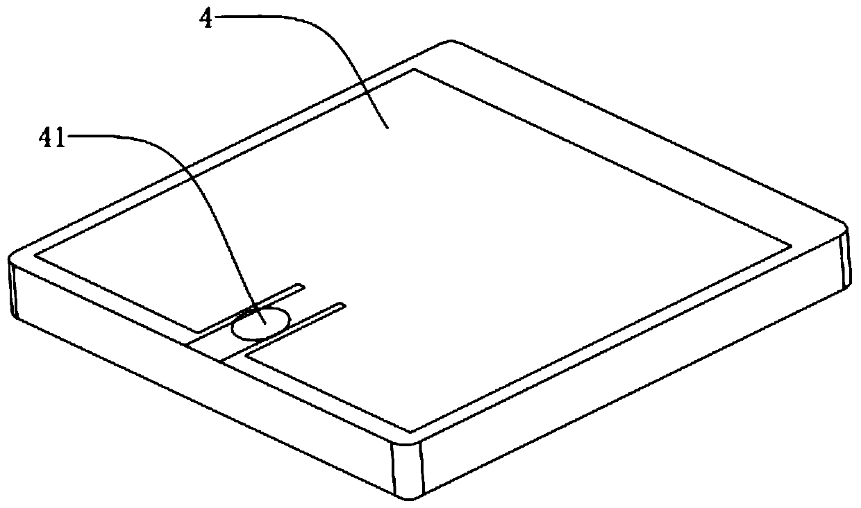
[0027] Such as figure 1 As shown, a temperature sensing device includes a fixed outer casing 1 and a hoop 2 fixedly connected with the fixed outer casing 1 . An RFID tag 4 is arranged in the fixed outer casing 1 (see image 3 ) and a base for enclosing the RFID tag 4 in the fixed outer casing 1. An RFID temperature measuring chip 41 for temperature detection is arranged on the RFID tag 4 , and the base is located on the side of the fixed outer cas...


PUM


Abstract

The invention discloses a temperature sensing device and a ring main unit temperature monitoring system. The invention relates to the technical field of ring main unit cable temperature monitoring. The temperature sensing device comprises a fixed outer shell and a hoop fixedly connected with the fixed outer shell. An FRID label and a base are arranged in the fixed outer shell, the base seals the FRID label in the fixed outer shell, an FRID temperature measuring chip used for temperature detection is arranged on the FRID label, and the base is located in the side, close to the hoop, of the fixed outer shell. According to the invention, a wireless passive temperature sensor is fixed to the sleeve through the hoop to monitor the temperature in the ring main unit in real time; and through arrangement of an alarm, when the temperature exceeds a preset temperature value, the alarm gives an alarm to prompt a manager to carry out cooling, so that the problem of ring main unit damage or fire accidents caused by internal temperature rise of the ring main unit is solved in time, and the damage probability of ring main unit equipment is remarkably reduced.

Description

technical field [0001] The present application relates to the technical field of ring network cabinet cables, in particular to a temperature sensing device and a ring network cabinet temperature monitoring system. Background technique [0002] The ring network cabinet is a group of electrical equipment for transmission and distribution that is installed in a metal or non-metal insulated cabinet or made into an assembled interval ring network power supply unit. Its core part uses load switches and fuses. It has simple structure, small size, It has the advantages of low price, improved power supply parameters and performance, and power supply security. [0003] As a wireless transmission technology, RFID technology has expanded its application of radio frequency identification tags from just transmitting data stored in tags to indicate its identity to more and more application fields. For example, when transmitting the data representing the identity, the ambient temperature d...

Claims


Application Information

Patent Timeline
IPC IPC(8): G01K7/00G01K1/12G01K1/02G01K1/024
CPCG01K7/00G01K1/12G01K1/02
Inventor 王辉东邢海清杨嘉玮韩辉冯姗姗胡水军曹利徐华
Owner HANGZHOU ELECTRIC EQUIP MFG
Learn More