Axle system thermal characteristic analysis method based on analytical method, thermal error modeling method and thermal error compensation system

An analysis method and technology of thermal characteristics, applied in complex mathematical operations, geometric CAD, design optimization/simulation, etc., can solve problems such as the inability to obtain the thermal characteristics of the shaft system

Active Publication Date: 2020-06-19
CHONGQING UNIV
View PDF6 Cites 5 Cited by
  • Summary
  • Abstract
  • Description
  • Claims
  • Application Information

AI Technical Summary

Problems solved by technology

[0003] The Chinese patent application with the publication number CN1948775 discloses a method and device for adjusting the bearing preload by using the thermal characteristics of metal materials. The method can obtain relatively accurate design parameters and provide design parameters for the device for adjusting the bearing preload. However, the thermal characteristics of the shaft system cannot be obtained

Method used


Image

  • Axle system thermal characteristic analysis method based on analytical method, thermal error modeling method and thermal error compensation system
  • Axle system thermal characteristic analysis method based on analytical method, thermal error modeling method and thermal error compensation system
  • Axle system thermal characteristic analysis method based on analytical method, thermal error modeling method and thermal error compensation system

Examples


Embodiment 1

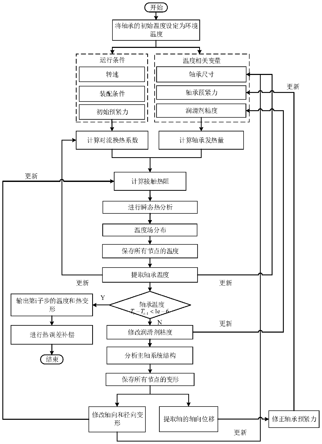
[0128] In this embodiment, the method for analyzing the thermal characteristics of the shaft system based on the analytical method includes the following steps:

[0129] 1) According to the heat balance principle, the heat balance equation of the rolling element of the shaft system is established, and the transient thermal characteristic model of the shaft system is established by the heat balance equation. The rolling elements of the shaft system of this embodiment include balls, inner rings and outer rings of the bearing.

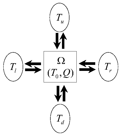
[0130] Specifically, the heat balance principle is: according to the temperature transfer principle of the shaft system, the heat balance equation for controlling the volume Ω is constructed:

[0131]

[0132] Among them, T Ω Indicates the temperature of the control volume; C indicates the specific heat capacity of the control volume; T l , T u , T r and T d Respectively represent the temperature of the object in contact with the control volume; R...

Embodiment 2

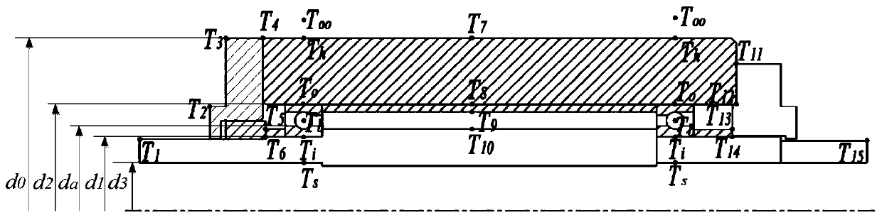
[0275] The shaft in the shaft system is heated by the thermal load of the front and rear bearings, and the shaft temperature can be expressed as

[0276]

[0277] Among them, T(x,t) represents the heat load at the position x on the axis at time t; T fb (x,t) and T rb (x, t) represent the heat load applied to the shaft by the front and rear bearings respectively; C 1 、C 2 、C 3 and C 4 Both are coefficients; h is the convection coefficient; λ is the core expansion coefficient; d is the diameter of the shaft; ρ is the density of the shaft; c is the specific heat capacity of the shaft;

[0278] For a shaft system with free ends, that is, at least one end of the shaft has only radial constraints and no axial constraints, the thermal expansion is:

[0279]

[0280] In the formula, α represents the axial thermal elongation coefficient; L represents the length of the shaft; T ∞ Indicates the ambient temperature.

[0281] Since the coefficient C cannot be determined 1 ,C ...

Embodiment 3

[0351] like Figure 19 As shown, the thermal error compensation system of the shaft system based on the analytical method in this embodiment includes:

[0352] CNC machining center, including PLC controller and temperature sensor;

[0353] The data acquisition system is connected with the CNC machining center, and is used to collect the running speed information and running time information of the shaft system, and process the running speed information and running time information through filters, amplifiers and A / D converters to obtain the shaft The actual running time and speed of the system;

[0354] The thermal error compensation system is connected with the data acquisition system, and adopts the thermal error modeling method of the shaft system based on the analytical method described in embodiment 2 to calculate the thermal error, and obtain the compensation components of the shaft in each direction;

[0355] The PLC controller is connected to the thermal error compen...


PUM


Abstract

The invention discloses an axle system thermal characteristic analysis method based on an analytical method. The axle system thermal characteristic analysis method comprises the following steps: 1) creating a transient thermal characteristic model of a shaft system; 2) calculating the thermal load intensity of the bearing, the contact thermal resistance of all temperature nodes in the shaft systemand the initial value of the convective heat transfer coefficient of the lubricant according to the initial operating condition of the shaft system and the initial value of the temperature-related variable; 3) performing transient thermal analysis on the shaft system by utilizing the transient thermal characteristic model of the shaft system; 4) comparing the temperatures of the rolling elementsin two adjacent iteration sub-steps, if the temperatures meet the convergence condition, entering the step 5), and if the temperatures do not meet the convergence condition, entering the step 6); theshaft system thermal error modeling method comprises the following steps of (1) establishing a shaft system temperature field, (2) finishing analysis, (3) updating contact thermal resistance, a convective heat transfer coefficient and temperature-related variables through the shaft system temperature field, and (7) circulating the step (3) and the step (4) until convergence conditions are met, andfurther comprises an axle system thermal error modeling method and a thermal error compensation method.

Description

technical field [0001] The invention belongs to the technical field of thermal characteristic analysis, in particular to an analytical method-based thermal characteristic analysis method of a shaft system, a thermal error modeling method and a thermal error compensation system. Background technique [0002] The shaft system includes a shaft and bearings located at both ends of the shaft, bearing housings and bearing rings, etc. At present, bearing and lubrication are the main factors affecting the shaft speed range. In the shaft structure using contact bearings, the higher the shaft speed, the more serious the heat generation. Shaft heating is related to bearing preload. When the pre-tightening force is appropriate, the effect on the precision, stiffness, life, damping and noise reduction of the shaft bearing is more obvious. With the increase of the pre-tightening force, the friction increases, the heat increases, and the service life of the bearing is reduced. The main r...

Claims


Application Information

Patent Timeline
Patent Type & Authority Applications(China)
IPC IPC(8): G06F30/23G06F30/17G06F119/08G06F17/11
CPCG06F17/11
Inventor 马驰刘佳兰易力力王时龙
Owner CHONGQING UNIV
Why Eureka
Try Eureka