Silicon wafer feeding and discharging transmission system

A technology of transmission system and silicon wafer, which is applied in the field of solar cells, can solve the problems of low efficiency, achieve the effect of improving transmission efficiency, improving the efficiency of variable distance adjustment, and realizing accurate docking

Pending Publication Date: 2020-06-19
SUZHOU MAXWELL TECH CO LTD
View PDF0 Cites 3 Cited by
  • Summary
  • Abstract
  • Description
  • Claims
  • Application Information

AI Technical Summary

Problems solved by technology

[0007] The invention overcomes the disadvantage of low efficiency in the process of loading and unloading silicon wafers in the prior art, and provides a silicon wafer loading and unloading transmission system. The wafer positioning mechanism and the wafer pocket on the wafer carrier greatly improve the transmission efficiency and realize the accurate docking of wafer loading and unloading

Method used


Image

  • Silicon wafer feeding and discharging transmission system
  • Silicon wafer feeding and discharging transmission system
  • Silicon wafer feeding and discharging transmission system

Examples


Embodiment 1

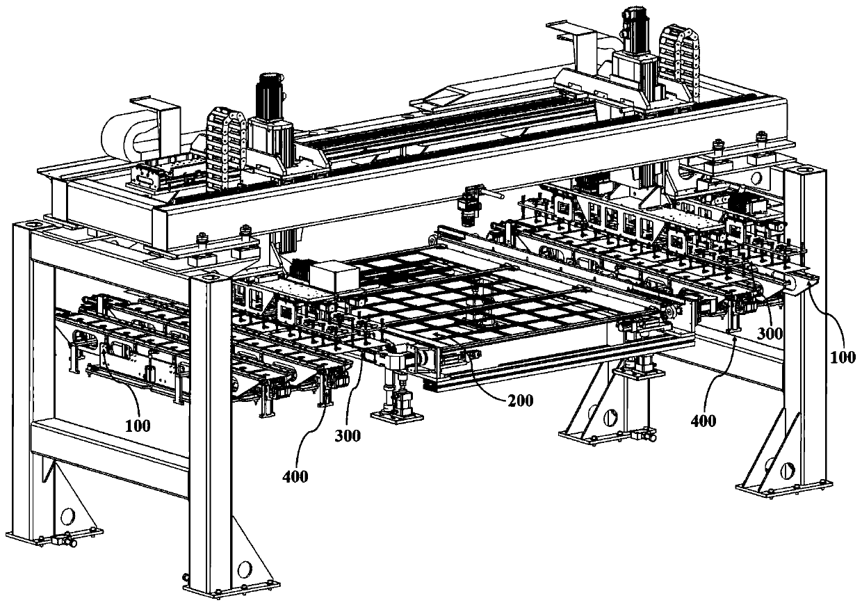
[0039] to combine Figure 5 , in the production of silicon wafers, it is necessary to take out the silicon wafers 500 piece by piece from the flower basket and put them on the silicon wafer carrier 200. Specifically, after the flower basket elevator is in place, it descends to send the silicon wafers 500 to the belt transmission mechanism 400, and the belt The transmission mechanism 400 includes a bracket 410 set at the bottom, on which is a drive shaft 411 for driving the conveyor belt 412 to move, the conveyor belt 412 picks up the silicon wafer 500 on the flower basket elevator and then is carried by the silicon wafer handling mechanism to carry it onto the wafer carrier 200.

[0040] The silicon wafer carrier 200 in the prior art can accommodate multiple silicon wafers 500 of the same specification at the same time, and the silicon wafers 500 are equidistantly arranged, and the silicon wafer handling mechanism only needs to carry the silicon wafers 500 in a certain directi...

Embodiment 2

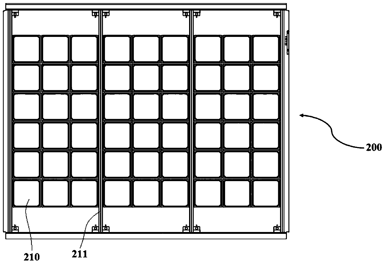
[0047] A silicon chip loading and unloading transmission system in this embodiment has basically the same structure as in Embodiment 1. Further, the grooves 210 in this embodiment are distributed in a rectangular array along the direction in which the support structure 211 is set, and two adjacent The grooves 210 between the support structures 211 are equidistantly distributed.

[0048] Specifically, in this embodiment, the silicon wafer carrier 200 is provided with grooves 210 in 6 rows*9 columns and four supporting structures 211, and a supporting structure 211 is provided every three columns, that is, the grooves on the silicon wafer carrier 200. The array of grooves 210 is divided into three groups of rectangular arrays by four support structures 211, and the grooves 210 between two adjacent support structures 211 are equally spaced, and the distance between every three columns of grooves 211 on the silicon wafer carrier 200 varies once.

[0049] In order to improve the p...

Embodiment 3

[0054] A silicon wafer loading and unloading transmission system in this embodiment has basically the same structure as that in Embodiment 2. Further, the distance changing mechanism 310 in this embodiment also includes a sensor 316, and the sensor 316 is arranged at the end of the distance changing slide rail 315 to It is used to detect the movement distance of the sliding seat 318 along the length direction of the suspension frame.

[0055] Specifically, in this embodiment, an induction sheet 317 is correspondingly provided on the side of the sliding seat 318 opposite to the sensor 316, and when the pitch-changing mechanism 310 drives the sucker assembly 320 to move to the sensor 316, the sensor 316 senses the induction on the sliding seat 318. Sheet 317, at this time, it shows that the distance variable mechanism 310 is in place, that is, the suction cup assemblies 320 connected to the bottom of the slide seat 318 are equidistantly distributed, and at this time, the sensor 3...


PUM


Abstract

The invention discloses a silicon wafer feeding and discharging transmission system, and belongs to the technical field of solar cells. The feeding and discharging transmission system comprises a silicon wafer positioning mechanism, a silicon wafer carrier, a silicon wafer variable-pitch carrying mechanism and a belt conveying mechanism, wherein the silicon wafer variable-pitch carrying mechanismis used for carrying silicon wafers from the silicon wafer positioning mechanism to the silicon wafer carrier or carrying the silicon wafers from the silicon wafer carrier to the belt conveying mechanism, and the silicon wafer variable-pitch carrying mechanism is used for carrying out variable-pitch adjustment on the silicon wafer so that the silicon wafer can be matched with the silicon wafer positioning mechanism and the silicon wafer pocket on the silicon wafer carrier respectively. The silicon wafer variable-pitch carrying mechanism can carry out variable-pitch adjustment on silicon wafersso as to adapt to the silicon wafer positioning mechanism and the silicon wafer pockets on the silicon wafer carrier, the transmission efficiency is greatly improved and accurate butt joint of feeding and discharging of the silicon wafers is achieved.

Description

technical field [0001] The invention belongs to the technical field of solar cells, and more specifically relates to a silicon wafer loading and unloading transmission system. Background technique [0002] In the prior art, the loading and unloading process of silicon wafers adopts a combination of manipulator pick-up and belt transmission, specifically: the silicon wafers to be processed are stored in the flower basket in advance, placed on the belt by the manipulator, and stored on the belt After a certain number of silicon wafers, the suction cup manipulator will pick up and place these silicon wafers on the tray for laminating at one time. After the lamination is completed, it will be put back on the belt through the suction cup manipulator, and finally transferred to the flower basket. The tray is a carrier for silicon wafers, which is used for carrying and transporting silicon wafers in vacuum equipment. The tray in the prior art is provided with grooves for carrying ...

Claims


Application Information

Patent Timeline
IPC IPC(8): H01L21/677H01L21/683
CPCH01L21/67706H01L21/6836
Inventor 董平博连建军李新丰王彦齐
Owner SUZHOU MAXWELL TECH CO LTD
Why Eureka
Try Eureka