Electric spark deposition mechanism for functional coating on inner wall of slender pipeline

A technology of EDM deposition and pipeline, applied in coating, metal material coating process and other directions, can solve the problems of poor deposition quality, low efficiency, and difficulty in manual EDM deposition, and achieve the effect of ensuring safety

Pending Publication Date: 2020-06-23
LANZHOU JIAOTONG UNIV
View PDF0 Cites 0 Cited by
  • Summary
  • Abstract
  • Description
  • Claims
  • Application Information

AI Technical Summary

Problems solved by technology

[0004] The purpose of the present invention is to solve the problems of difficult manual EDM deposition of functional coatings on the inner wall of slender pipes, poor deposition quality and low efficiency, thereby providing a mechanism for EDM deposition of functional coatings on the inner wall of slender pipes

Method used


Image

  • Electric spark deposition mechanism for functional coating on inner wall of slender pipeline
  • Electric spark deposition mechanism for functional coating on inner wall of slender pipeline
  • Electric spark deposition mechanism for functional coating on inner wall of slender pipeline

Examples


specific Embodiment approach 1

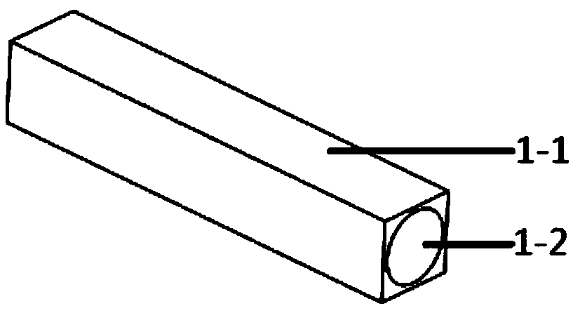
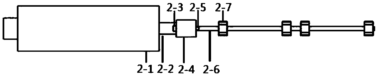
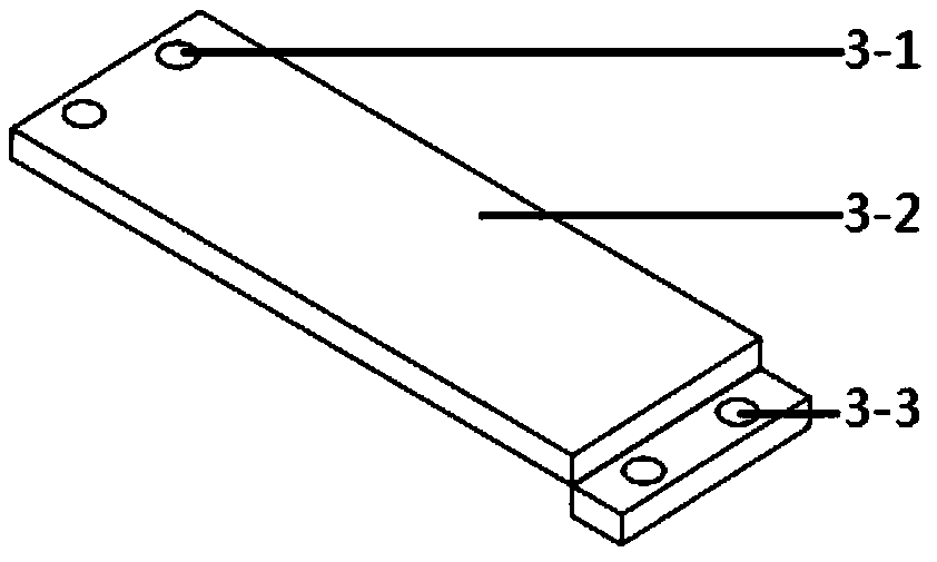
[0033] Specific embodiment 1: This embodiment is a kind of electrospark deposition mechanism of functional coating on the inner wall of a slender pipeline, which includes a support shaft (1), a cam rotation device (2), a primary supporting plate (3), and an electrode rotary vibration device (4). ), a shielding gas pipeline (5), a secondary pallet (6); the support shaft (1) includes a support shaft body (1-1) and a motor mounting part (1-2); the cam rotation device (2 ) including motor (2-1), motor rotating shaft (2-2), motor rotating shaft key (2-3), coupling (2-4), camshaft key (2-5), camshaft (2 -6) and cam (2-7); said primary pallet (3) includes threaded hole (3-1) connecting support shaft (1), primary pallet body (3-2) and fixed bracket ( 4-7) threaded hole (3-3); the electrode rotary vibration device (4) includes an electrode (4-1), a deposition power supply positive pole bearing (4-2), an electrode holder (4-3), Insulation sleeve (4-4), bolt (4-5), spring (4-6), bracket...

specific Embodiment approach 2

[0061] Specific embodiment 2: The difference between this embodiment and specific embodiment 1 is: the outer contour of the support shaft (1) is square, the inner contour is circular, and the material is aluminum alloy with good rigidity and light weight . Others are the same as the first embodiment.

specific Embodiment approach 3

[0062] Specific embodiment three: the difference between this embodiment and specific embodiment one or two is: the motor rotating shaft (2-2) and the camshaft (2-6) are connected by a shaft coupling (2-4) , the coupling (2-4) is connected to the motor rotating shaft (2-2) through the motor rotating shaft key (2-3), and the coupling (2-4) and the camshaft (2-6) are connected through the cam The shaft key (2-5) is connected, and the cam (2-7) is fixed on the camshaft (2-6) by the camshaft key (2-5). Others are the same as those in Embodiment 1 or 2.


PUM


Abstract

The invention relates to a mechanism, in particular to an electric spark deposition mechanism for a functional coating on the inner wall of a slender pipeline. The purpose is to solve the problems that manual electric spark deposition for the functional coating on the inner wall of the slender pipeline is difficult to carry out, the deposition quality is poor, and the efficiency is low. The electric spark deposition mechanism is based on modular design, and includes a supporting shaft, a cam rotating device, a primary supporting plate, an electrode rotating vibration device, a protective gas pipeline and a secondary supporting plate. Combined with a numerical control technology and an electric spark deposition surface strengthening technology, an electro spark deposition process platform for the functional coating of the inner wall of the slender pipeline is built, so that the numerical control and automatic deposition for the functional coating on the inner wall of the slender pipeline is realized. The electric spark deposition mechanism for the functional coating on the inner wall of the slender pipe is obtained.

Description

technical field [0001] The invention relates to a miniature deposition mechanism, in particular to an electric spark deposition mechanism for functional coating on the inner wall of a slender pipeline. Background technique [0002] Due to its excellent quality (such as: the coating is metallurgically bonded to the substrate; the residual stress of the deposited layer is small, the deformation is small; the deposition process is simple, the coating structure is fine, etc.), in aviation, aerospace, military industry, automobiles, tools, etc. , Die and other fields are increasingly widely used. However, the EDM deposition of the functional coating on the inner wall of the slender pipe is still performed manually, which is extremely inconvenient, the deposition efficiency and automation are low, and the deposition quality is unstable. The existence of the above problems seriously limits the application of this technology in the field of electrospark deposition of functional coa...

Claims


Application Information

Patent Timeline
IPC IPC(8): C23C26/02
CPCC23C26/02
Inventor 王朝琴王国钰汪瑞军王小荣刘晓琴何鹏罗冠炜
Owner LANZHOU JIAOTONG UNIV
Why Eureka
Try Eureka