
Connection structure between drainage tunnel and main line tunnel

A technology of drainage tunnels and main lines, applied in tunnels, drainage, safety devices, etc., can solve problems such as insufficient drainage capacity of drainage ditches and high water pressure

Pending Publication Date: 2020-06-23
中铁二院贵阳勘察设计研究院有限责任公司
View PDF0 Cites 3 Cited by
  • Summary
  • Abstract
  • Description
  • Claims
  • Application Information

AI Technical Summary

Problems solved by technology

[0002] In the construction of tunnels in karst rock areas, because the existing survey technology cannot accurately ascertain the development of karst and groundwater around the tunnels in karst areas, karst passages and underground rivers are often encountered during tunnel construction, resulting in insufficient drainage capacity of the originally designed drainage ditches or Withstand excessive water pressure, additional drainage channels need to be built

Method used


Image

  • Connection structure between drainage tunnel and main line tunnel
  • Connection structure between drainage tunnel and main line tunnel
  • Connection structure between drainage tunnel and main line tunnel

Examples


Embodiment Construction

[0015] The present invention will be further described below in conjunction with the accompanying drawings and embodiments.

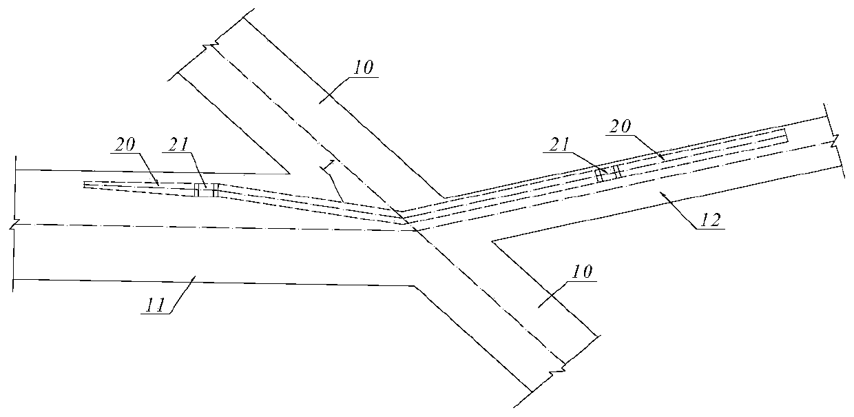
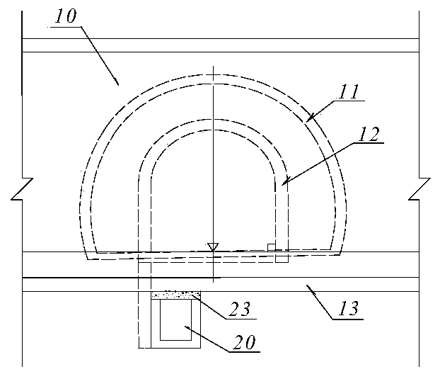
[0016] refer to figure 1 , figure 2 with image 3 , a connection structure between a drain tunnel and a mainline tunnel of the present invention, comprising a mainline tunnel 10, an existing horizontal tunnel 11 on one side thereof, a new drainage tunnel 12, a drainage ditch 20 and a water collection well 21. The other side of the main line tunnel 10 is provided with a newly built drainage tunnel 12, the newly built drainage tunnel 12, the existing horizontal hole 11 and the main line tunnel 10 form an intersection, and the lining structure of the main line tunnel 10 is drawn under the inverted arch 13. Groove excavation and construction of the drainage ditch 20, the two ends of the drainage ditch 20 respectively extend to the new drainage tunnel 12, the existing horizontal hole 11 and the water collection well 21 is set, and the concrete is set abov...


PUM


Abstract

The invention discloses a connection structure between a drainage tunnel and a main line tunnel so as to avoid large-scale downward excavation at the intersection of an existing transverse tunnel anda main tunnel, reduce the impact on the existing transverse tunnel and the main line tunnel, effectively reduce the construction safety risk of deep foundation pit support in the tunnel, reduce the interference to the main tunnel and transverse tunnel construction, shorten the construction period of a project, and save the project investment. The connection structure comprises the main line tunneland the existing transverse tunnel located on one side of the main line tunnel, the new-built drainage tunnel is arranged on the other side of the main line tunnel, and the new-built drainage tunneland the existing transverse tunnel form an intersection with the main line tunnel; and groove broaching, excavating and constructing of a drainage ditch are conducted under the inverted arch of a lining structure of the main line tunnel, the two ends of the drainage ditch extend into the new-built drainage tunnel and the existing transverse tunnel, a water collecting well is arranged, and a concrete filling layer is arranged from the upper part of the drainage ditch to the inverted arch of the lining structure.

Description

technical field [0001] The invention relates to a tunnel, in particular to a connection structure between a drainage tunnel and a mainline tunnel. Background technique [0002] In the construction of tunnels in karst rock areas, because the existing survey technology cannot accurately ascertain the development of karst and groundwater around the tunnels in karst areas, karst passages and underground rivers are often encountered during tunnel construction, resulting in insufficient drainage capacity of the originally designed drainage ditches or If the water pressure is too high, additional drainage channels need to be built. If it is revealed that karst passages, underground rivers, etc. are located close to the tunnel entrance, most of them adopt the solution of building parallel drainage tunnels; The option of building a new shorter horizontal hole or using the original designed horizontal hole for drainage will be considered. When building a new horizontal tunnel or usi...

Claims


Application Information

Patent Timeline
Patent Type & Authority Applications(China)
IPC IPC(8): E21D9/14E21F16/02
CPCE21D9/14E21F16/02
Inventor 杨刚方钱宝王小浪周忠德逄迎生陈思宇陈力周昊烜牛国栋霍建勋夏烈
Owner 中铁二院贵阳勘察设计研究院有限责任公司
Learn More