Supercharge Your Innovation With Domain-Expert AI Agents!

Renewable fuel cell

A fuel cell, fuel cell unit technology, applied in the direction of fuel cells, circuits, electrical components, etc., to achieve the effect of compact structure, long life and small volume

Active Publication Date: 2020-06-23
DALIAN INST OF CHEM PHYSICS CHINESE ACAD OF SCI
View PDF7 Cites 0 Cited by
  • Summary
  • Abstract
  • Description
  • Claims
  • Application Information

AI Technical Summary

Problems solved by technology

This patent only introduces the structure of the flow field plate and the semi-permeable membrane module

Method used


Image

  • Renewable fuel cell
  • Renewable fuel cell
  • Renewable fuel cell

Examples


Embodiment 1

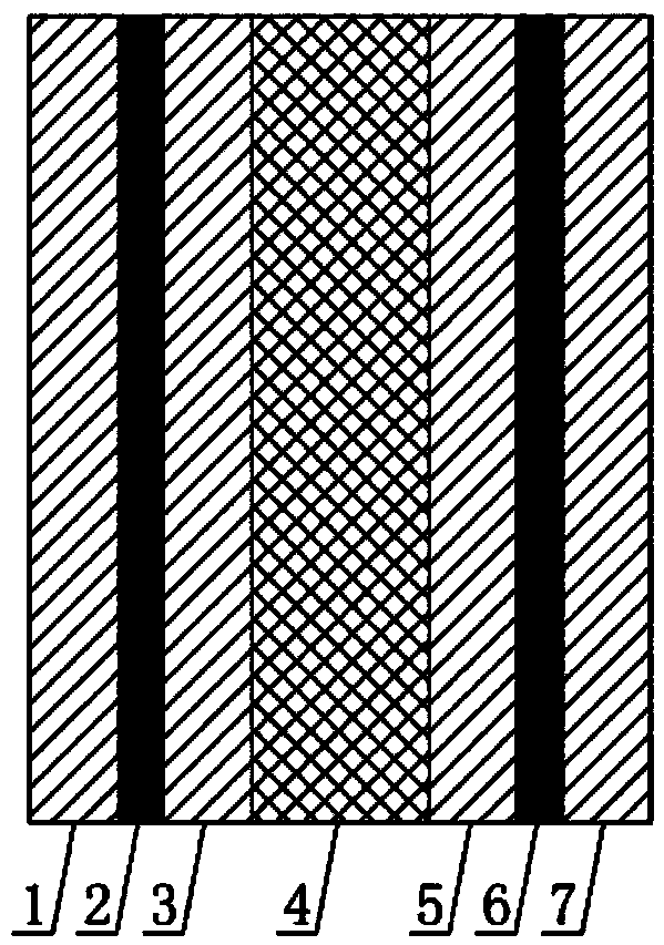
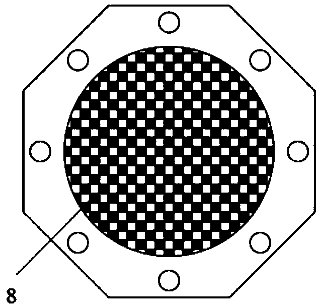
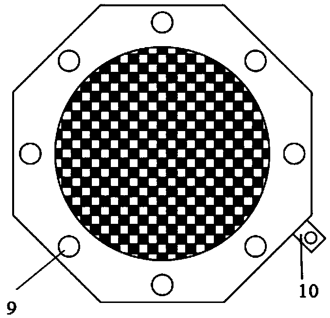
[0036] Specifically, the renewable fuel cell prepared in this embodiment is: the fuel cell unit includes: a fuel cell anode plate, a fuel cell membrane electrode assembly, and a fuel cell cathode plate. Among them, the fuel cell membrane electrode assembly contains Pt catalysts, and the fuel cell cathode plate is a non-metallic microporous plate of 0.2 μm, which is an integrated structure. The area of ​​the fuel cell electrode is larger than the area of ​​the non-metallic microporous plate; the water plate has two There are sealing rings on both sides of the water plate, and each cavity of the water plate is a dot-shaped hollow structure, such as figure 2Shown; Water electrolysis unit comprises: water electrolysis cell anode plate, water electrolysis cell membrane electrode assembly, water electrolysis cell cathode plate, wherein, water electrolysis cell membrane electrode assembly contains Ir catalyst and Pt catalyst, water electrolysis cell cathode plate is an opening 60% o...


PUM

PropertyMeasurementUnit
pore sizeaaaaaaaaaa
pore sizeaaaaaaaaaa
pore sizeaaaaaaaaaa

Abstract

The invention relates to a renewable fuel cell, which specifically comprises a plurality of fuel cell units and water electrolysis cell units, wherein the fuel cells and the water electrolysis cell units are overlapped together through water plates to form the renewable fuel cell with a fuel cell function and a water electrolysis tank function, the fuel cell has a non-attitude drainage capacity, and the water electrolysis tank has a non-attitude water supply capacity. The renewable fuel cell is small in size, long in service life and suitable for long-term operation in a microgravity environment.

Description

technical field [0001] The invention relates to the technical field of renewable fuel cells (RFC), and mainly relates to a combined structure of a proton exchange membrane fuel cell and a solid polymer electrolyte water electrolysis cell. Background technique [0002] With the high attention to space technology in the world, space power supply technology has developed rapidly. A highly safe and reliable space power supply system is an important factor to ensure the normal operation of space vehicles such as satellites. On the one hand, the power supply system is used to control the attitude of space vehicles such as satellites, and at the same time, it ensures the normal operation of instruments and equipment carried by space vehicles such as satellites and the communication with the ground. Improving the performance and cost performance of space power supplies is of great significance to increasing the payload and improving satellite performance and efficiency. [0003] R...

Claims


Application Information

Patent Timeline
Patent Type & Authority Applications(China)
IPC IPC(8): H01M8/0247H01M8/2455
CPCH01M8/0247H01M8/2455Y02E60/50
Inventor 孙树成李新韦世慧俞红梅邵志刚
Owner DALIAN INST OF CHEM PHYSICS CHINESE ACAD OF SCI
Features
  • R&D
  • Intellectual Property
  • Life Sciences
  • Materials
  • Tech Scout
  • Unparalleled Data Quality
  • Higher Quality Content
  • 60% Fewer Hallucinations
Learn More