Electric energy transmission connector and preparation method thereof

A technology of power transmission and integration, which is applied in the direction of conductive connection, contact manufacturing, and connection contact materials, etc., can solve the problems of high production cost of power transmission copper parts, increase equipment tooling cost, and not easy to automate production, so as to save processing Time, quick and easy production, weight reduction effect

Pending Publication Date: 2020-06-23
JILIN ZHONG YING HIGH TECH CO LTD
View PDF0 Cites 4 Cited by
  • Summary
  • Abstract
  • Description
  • Claims
  • Application Information

AI Technical Summary

Problems solved by technology

Power transmission copper parts are generally solid, which is a waste of material, and solid power transmission copper parts are generally processed by hot forging, which consumes high energy, has large processing errors, and the production cost of power transmission copper parts is high.
Moreover, when copper parts of different shapes for power transmission are connected to aluminum wires by welding, different fixtures need to be used, which increases costs and complicates the management of fixtures.
In addition, when welding, the aluminum wire is also welded in the welding equipment. Because the aluminum wire is relatively long and soft, it not only increases the cost of equipment tooling, but also is not easy to realize automatic production and loading and unloading. After welding, due to the aluminum Wire cannot be rotated to remove welding flash

Method used


Image

  • Electric energy transmission connector and preparation method thereof
  • Electric energy transmission connector and preparation method thereof
  • Electric energy transmission connector and preparation method thereof

Examples


Embodiment Construction

[0033] In order to further elaborate the technical means and effects that the present invention adopts for reaching the intended invention purpose, below in conjunction with the accompanying drawings and preferred embodiments, the specific implementation, structure, features and effects of the present invention are described in detail as follows:

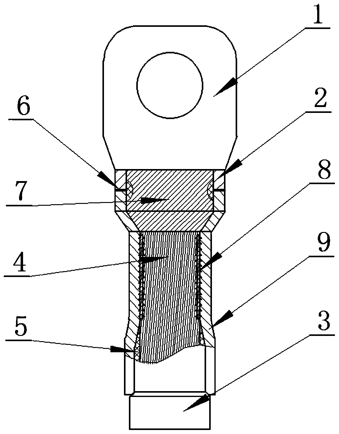
[0034] Such as figure 1 , the invention discloses a power transmission joint, which includes a power transmission copper part, a power transmission aluminum part 9 and an aluminum wire 3, the power transmission copper part includes a fixing part 1 for connecting an electrical device and a The connection part 2 of the aluminum part 9 for power transmission, the second through hole is provided inside the connection part 2, the first through hole is provided inside the aluminum part 9 for power transmission, and the insulation layer is stripped off at the front end of the aluminum wire 3 5 and then extend into the cavity formed by the ...


PUM

PropertyMeasurementUnit
mechanical propertiesaaaaaaaaaa

Abstract

The invention discloses an electric energy transmission connector and a preparation method thereof. The electric energy transmission connector comprises an electric energy transmission copper piece, an electric energy transmission aluminum piece and an aluminum wire. The electric energy transmission copper piece comprises a fixing piece used for being connected with an electric device and a connecting piece used for being connected with the electric energy transmission aluminum piece, a first through hole is formed in the electric energy transmission aluminum piece, a second through hole is formed in the connecting piece, an aluminum conducting core exposed after an insulating layer is stripped from the front end of the aluminum conducting wire extends into a cavity formed by connecting the first through hole and the second through hole, and the electric energy transmission aluminum piece is connected with the aluminum conducting wire in a crimping mode. The electric energy transmission copper piece is light in weight and rapid in production, and the production cost is saved. And moreover, the feeding and discharging automation of the electric energy transmission copper part and the electric energy transmission aluminum part can be realized, and the flash generated during welding is directly cut off after welding, so that the processing time is saved, and the assembly efficiency is greatly improved.

Description

technical field [0001] The invention relates to the technical field of electrical connection, in particular to an electric energy transmission joint and a preparation method thereof. Background technique [0002] At present, under the premise of reducing the weight of the wiring harness, aluminum wires will be used in large quantities. However, since most of the terminals of electrical devices are still made of copper, aluminum wires must be connected to copper parts for power transmission. Power transmission copper parts are generally solid, which is a waste of material, and solid power transmission copper parts are generally processed by hot forging, which consumes high energy, has large processing errors, and the production cost of power transmission copper parts is high. . Moreover, when the copper parts for power transmission of different shapes are connected to the aluminum wires by welding, different fixtures need to be used, which increases the cost and complicates ...

Claims


Application Information

Patent Timeline
Patent Type & Authority Applications(China)
IPC IPC(8): H01R11/11H01R4/62H01R4/20H01R43/02H01R43/048H01R43/16
CPCH01R11/11H01R4/62H01R4/625H01R4/20H01R43/02H01R43/0482H01R43/16H01R11/12H01R43/28H01R4/187H01R43/04
Inventor 王超
Owner JILIN ZHONG YING HIGH TECH CO LTD
Why Eureka
Try Eureka