Hardware paint spraying and drying robot

A technology of robots and hardware, applied in spray booths, spray devices, pre-treated surfaces, etc., can solve the problem that the clamping part is not sprayed, and achieve the effect of avoiding solidification

Active Publication Date: 2020-06-26
义乌市佳倩科技有限公司
View PDF11 Cites 3 Cited by
  • Summary
  • Abstract
  • Description
  • Claims
  • Application Information

AI Technical Summary

Problems solved by technology

[0004] For the existing hardware painting and drying robot, when painting the hardware, the hardware needs to be fixed and clamped. Since the clamping head is in contact with the surface of the hardware accessories,

Method used


Image

  • Hardware paint spraying and drying robot
  • Hardware paint spraying and drying robot
  • Hardware paint spraying and drying robot

Examples


Embodiment 1

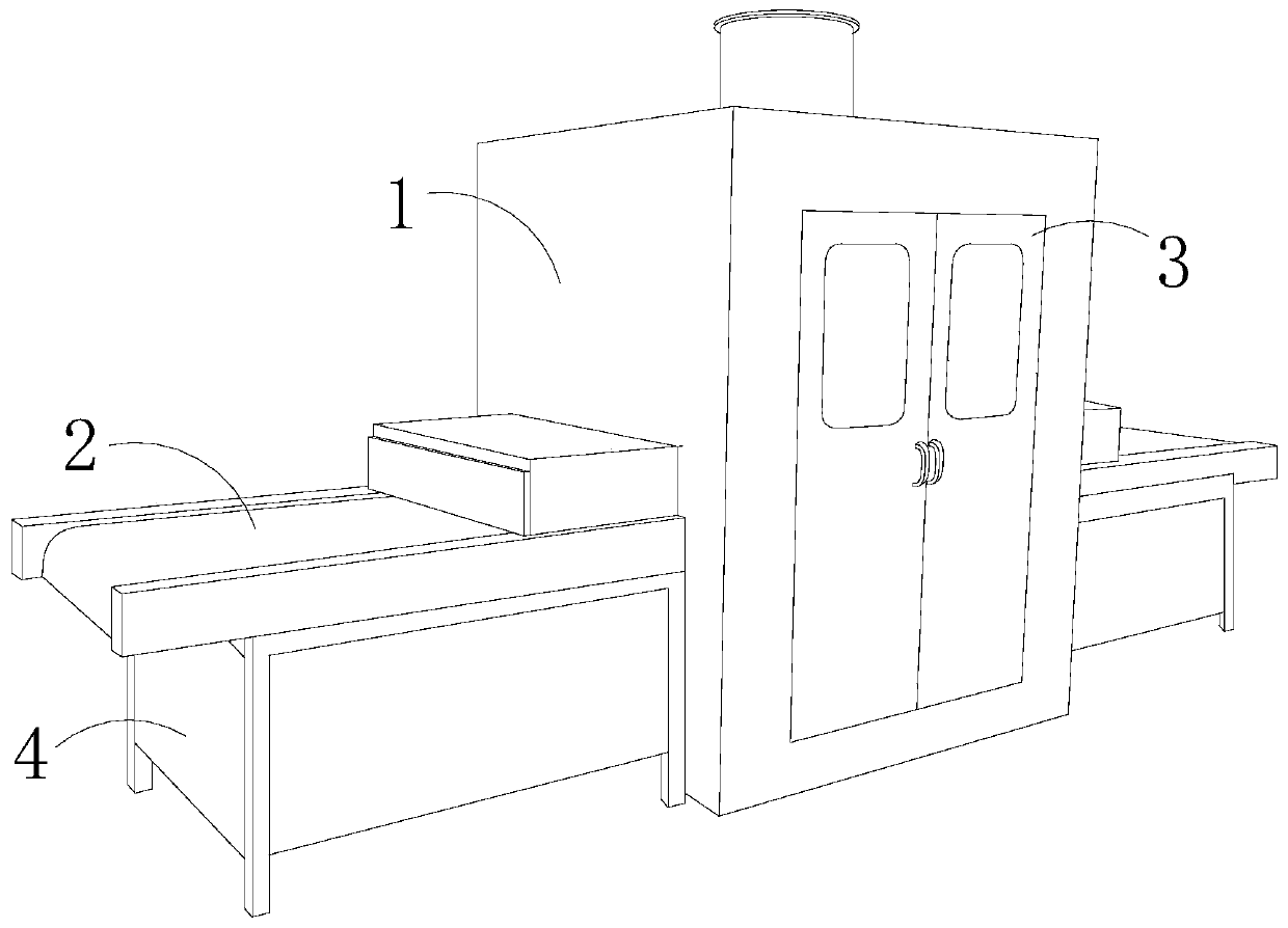
[0028] see Figure 1-Figure 5 :

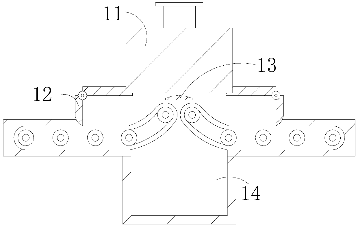
[0029] A metal spraying and drying robot, its structure includes a processing cabinet 1, a conveyor belt 2, a box door 3, and a base 4, the processing cabinet 1 is connected to the middle of the base 4 by welding, the conveyor belt 2 is installed above the base 4, and the The box door 3 is mounted on the front end of the processing cabinet 1. The processing cabinet 1 includes a paint drying chamber 11, a valve 12, a guide plate 13, and a miscellaneous storage chamber 14. The paint spray drying chamber 11 is embedded in the upper inner wall of the processing cabinet 1. The valve 12 is connected to both sides of the processing cabinet 1 through hinges, the guide plate 13 is connected to the inside of the processing cabinet 1 by welding and placed at the bottom of the paint drying chamber 11, and the miscellaneous storage chamber 14 is installed on the lower inner wall of the processing cabinet 1. The end of the conveyor belt 2 is connected to b...

Embodiment 2

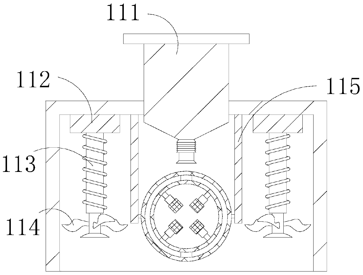
[0035] see Figure 6-Figure 8 :

[0036]In the figure, the paint storage cylinder 111 includes an upper cover b1, a stirring paddle b2, an adjustment device b3, a lower plug b4, and a paint spray tube b5. The upper cover b1 is fitted on the upper surface of the paint storage cylinder 111. The top of b2 is connected to the bottom of the upper cover b1 by welding, the adjustment device b3 is installed at the end of the stirring paddle b2, the lower plug b4 is located below the adjustment device b3, and the paint spray pipe b5 is embedded in the bottom of the paint storage cylinder 111. The size of the lower plug b4 is matched with the inside of the paint spray pipe b5 to prevent the paint spray from solidifying inside the paint storage cylinder 111.

[0037] In the figure, the adjustment device b3 includes a concave-convex block b31, a guide rail b32, a roller b33, a support block b34, a limit plate b35, and a support rod b36. Set on the lower surface of the concave-convex blo...


PUM


Abstract

The invention discloses a hardware paint spraying and drying robot. The hardware paint spraying and drying robot structurally comprises a machining cabinet, a conveying belt, box doors and a base. Themachining cabinet comprises a paint spraying and drying cavity, valves, a guide plate and an impurity storage cavity. The paint spraying and drying cavity comprises a paint storage barrel, heating plates, heating pipes, drying fans and an object device. The object device comprises a horizontal rotating rod, a locating outer shell, vertical rotating rods, a locating inner shell and clamping blocks. The clamping blocks comprise fixed blocks, rotating wheels, supporting springs and fixed rods. The paint storage barrel comprises an upper cover, a stirring paddle, an adjusting device, a discharging plug and a paint spraying pipe. The adjusting device comprises a concave-convex block, a guide rail, rolling wheels, a supporting block, a limiting plate and a supporting rod. Each rolling wheel comprises a clamp plate, a rubber block and a ball. Hardware needing paint spraying is placed on the object device, under the action of the supporting spring, the hardware is clamped by the clamping blocks, the hardware is prevented from falling off during paint spraying, clamping faces are changed, all the faces of the hardware can be sprayed with paint, and therefore oxidization rusting of the hardware is avoided, and the attractiveness of the hardware is improved.

Description

technical field [0001] The invention relates to the field of hardware painting processing, in particular to a hardware painting drying robot. Background technique [0002] With the development of industrialization, hardware has become an indispensable must-have in people's life. When processing hardware, use a hardware spraying and drying robot to spray paint and dry the hardware, so as to prevent the oxidation and rust of the hardware and improve the quality of the hardware. Aesthetics of the piece. [0003] At present, the existing hardware spraying and drying robot needs to fix and clamp the hardware when spraying the hardware. Since the clamping head is in contact with the surface of the hardware, the clamping part is not painted, and the hardware needs to be removed. Then paint it a second time. Contents of the invention [0004] For the existing hardware painting and drying robot, when painting the hardware, the hardware needs to be fixed and clamped. Since the cla...

Claims


Application Information

Patent Timeline
IPC IPC(8): B05B16/20B05B13/02B05B15/25B05D3/04
CPCB05B13/0228B05D3/0413B05B15/25B05B16/20
Inventor 洪沧龙
Owner 义乌市佳倩科技有限公司
Why Eureka
Try Eureka