Sheet steel punching device

A technology of steel sheet and steel strip, applied in the direction of feeding device, positioning device, storage device, etc., can solve the problems of steel strip twisting, complicated operation, large floor space, etc.

Pending Publication Date: 2020-06-26
SUZHOU LANGKUN AUTOMATION EQUIP CO LTD
View PDF0 Cites 2 Cited by
  • Summary
  • Abstract
  • Description
  • Claims
  • Application Information

AI Technical Summary

Problems solved by technology

[0002] At present, steel strip processing includes processes such as feeding, feeding, positioning, cutting, and cover film recycling. It requires multiple equipments to be used together, which occupies a large area and costs high. In order to meet the processing accuracy of each station, the product needs to be processed many times. The positioning and operation are complicated. The left and right positions are easy to deviate during the feeding process of the steel belt. The sheet is skewed, too long, too short or twisted. The pulling force of the ordinary turntable type will affect the cutting. After the steel strip is cut, the middle part is cut off, and the recovery of the steel strip after cutting is difficult to ensure smooth collection. , long-term extrusion occurs, that is, the two ends of the steel strip are offset to the middle, which indirectly affects the cutting of the upper steel strip. Based on the above defects and deficiencies, it is necessary to improve the existing technology and design a steel sheet punching device

Method used


Image

  • Sheet steel punching device
  • Sheet steel punching device
  • Sheet steel punching device

Examples


Embodiment Construction

[0026] The preferred embodiments of the present invention will be described in detail below in conjunction with the accompanying drawings, so that the advantages and features of the invention can be more easily understood by those skilled in the art, so as to define the protection scope of the present invention more clearly.

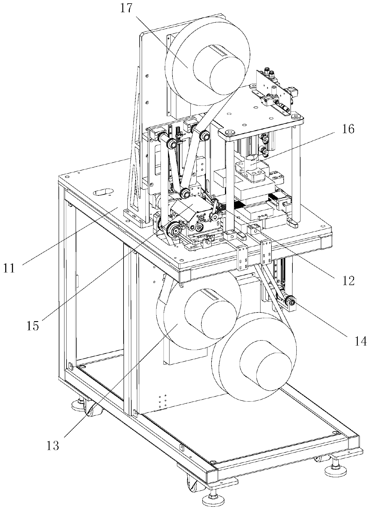
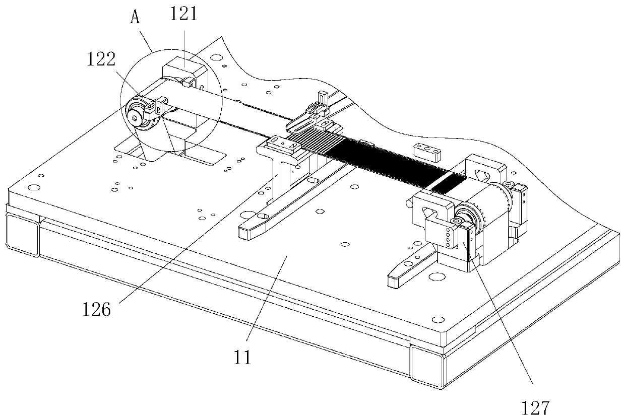
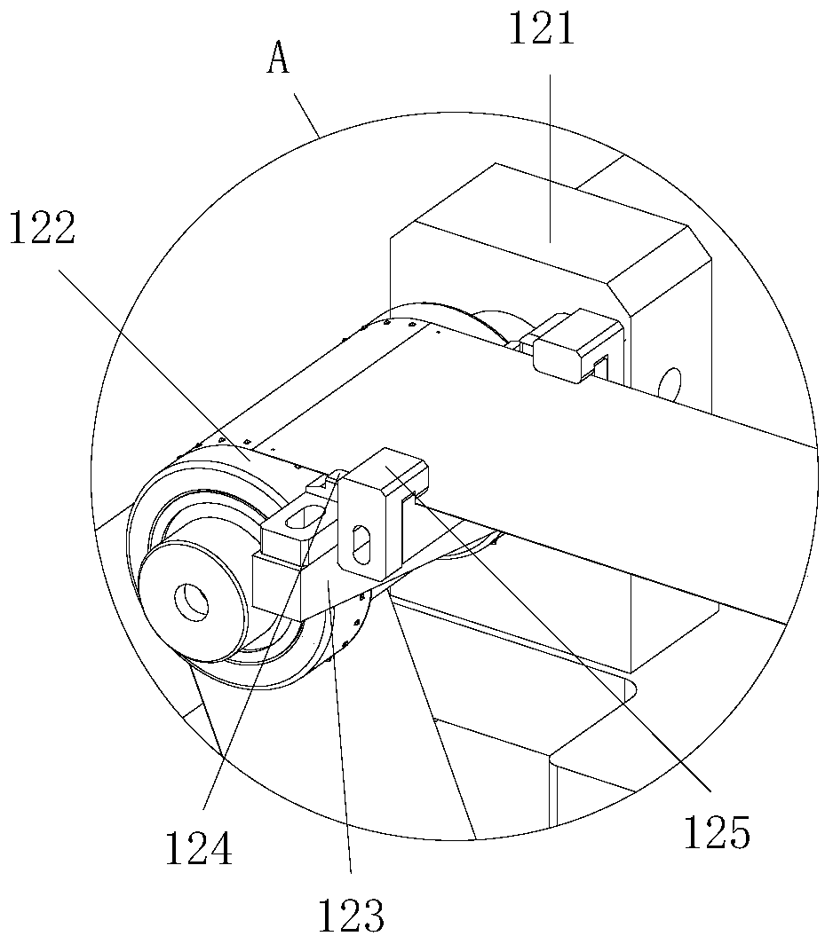
[0027] see Figure 1 to Figure 9 , the embodiment of the present invention includes:

[0028] A steel sheet punching device, the steel sheet punching device includes a punching bracket 11, a steel strip positioning assembly 12, a steel strip feeding tray 13, a steel strip feeding mechanism 14, a bottom paper receiving mechanism 15, and a cutting machine 16 and the cover film reclaiming material tray 17, a steel strip positioning assembly 12 is installed on the workbench of the punching support 11, a steel strip feeding mechanism 14 is arranged on the front end of the steel strip positioning assembly 12, and a cutting strip is provided on the steel strip ...


PUM


Abstract

The invention discloses a sheet steel punching device. The sheet steel punching device comprises a punching support, a steel strip positioning assembly, a steel strip material tray, a steel strip feeding mechanism, a backing paper material receiving mechanism, a cutting machine and a cover film retrieving material tray. The steel strip feeding mechanism is arranged at the front end of the steel strip positioning assembly in a butt joint manner. The cutting machine is arranged on the steel strip positioning assembly. The steel strip material tray and the backing paper material receiving mechanism are arranged at the bottom of the punching support. A steel strip on the steel strip material tray is conveyed to the backing paper material receiving mechanism after passing by the steel strip feeding mechanism and the steel strip positioning assembly. The cover film retrieving material tray is arranged on a workbench of the punching support. A cover film on the steel strip is retrieved into the cover film retrieving material tray. In this way, the sheet steel punching device can position the steel strip in the conveying process, and the flatness of the steel strip during cutting is guaranteed while pull damage caused to the steel strip by punching cutting is avoided; because feeding is carried out in an extrusion manner, the sheet steel punching device can adapt to feeding of steel strips of different thicknesses, it can be avoided that the steel strip runs helter-skelter, and it can be prevented that cutting is affected by the force of retrieving materials.

Description

technical field [0001] The invention relates to the technical field of steel strip processing, in particular to a steel sheet punching device. Background technique [0002] At present, steel strip processing includes processes such as feeding, feeding, positioning, cutting, and cover film recycling, which require multiple equipments to be used together, occupying a large area and high cost. In order to meet the processing accuracy of each station, the product needs to be processed many times. The positioning and operation are complicated. The left and right positions are prone to deviation during the feeding process of the steel belt. The sheet is skewed, too long, too short or twisted, and the pulling force of the ordinary turntable feeding will affect the cutting. After the steel strip is cut, the middle part is cut off, and the recovery of the steel strip after cutting is difficult to ensure smooth collection. , long-term extrusion occurs, that is, the two ends of the st...

Claims


Application Information

Patent Timeline
Patent Type & Authority Applications(China)
IPC IPC(8): B21D28/02B21D43/20B21D43/13B21D43/02B21D28/04B21C51/00B08B17/02
CPCB08B17/02B21C51/00B21D28/02B21D28/04B21D43/021B21D43/023B21D43/13B21D43/20
Inventor 王柱佟云辉谢桥清陈海林郑贵军
Owner SUZHOU LANGKUN AUTOMATION EQUIP CO LTD
Why Eureka
Try Eureka