Method for controlling hydraulic brake system and corresponding device

A hydraulic brake and hydraulic fluid technology, applied in the field of hydraulic brake systems, can solve problems such as not directly affecting the step-down gradient, achieve good wheel observability, reduce volume consumption, and improve braking performance

Active Publication Date: 2020-06-26
ROBERT BOSCH GMBH
View PDF4 Cites 1 Cited by
  • Summary
  • Abstract
  • Description
  • Claims
  • Application Information

AI Technical Summary

Problems solved by technology

However, by using an on-off valve, the desired step-down gradient during the opening phase cannot be directly influenced

Method used


Image

  • Method for controlling hydraulic brake system and corresponding device
  • Method for controlling hydraulic brake system and corresponding device
  • Method for controlling hydraulic brake system and corresponding device

Examples


Embodiment Construction

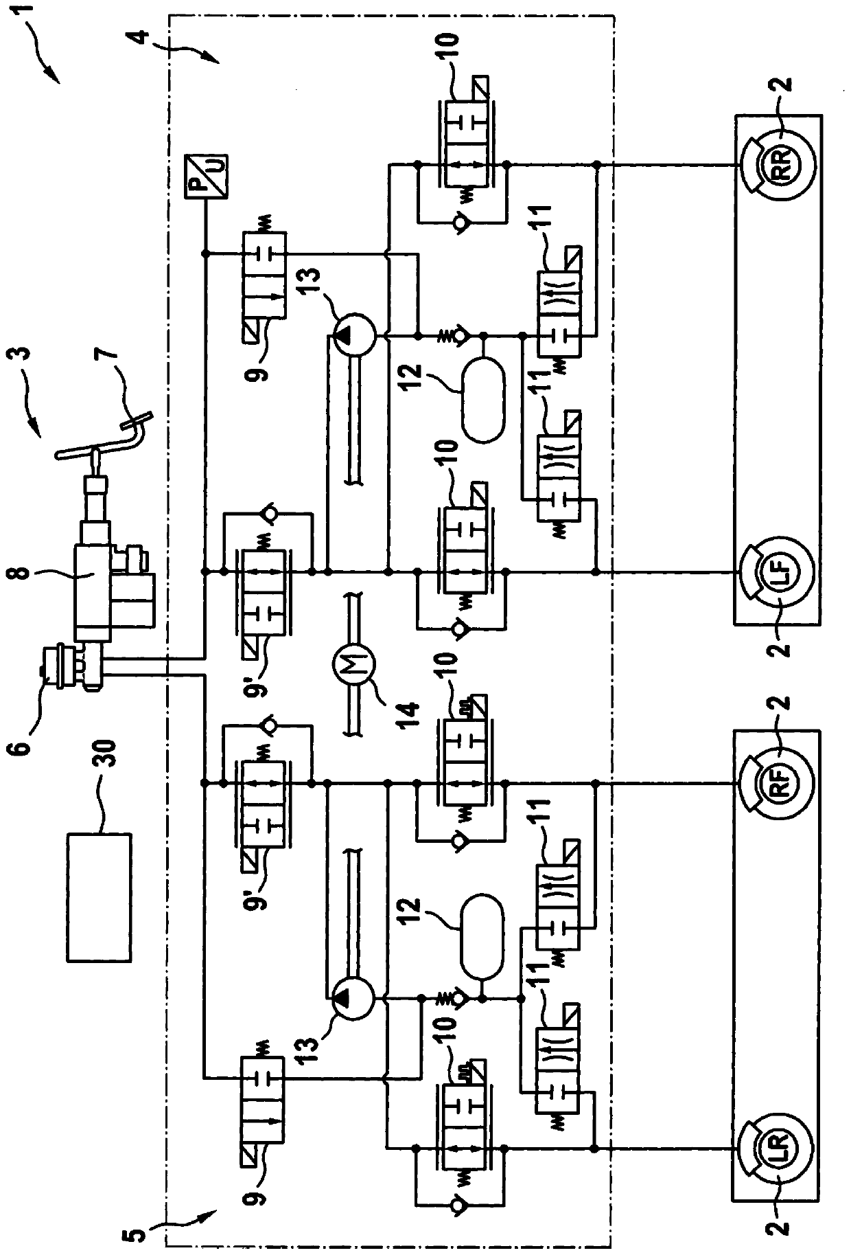
[0041] figure 1 A simplified diagram of a brake system 1 for a motor vehicle (not shown in detail) is shown. Brake system 1 has a plurality of wheel brakes 2 which can be actuated by a driver of the motor vehicle by means of a brake pedal device 3 as an actuation brake. The wheel brakes 2 are labeled LR, RF, LF and RR, thereby indicating their position or correspondence on the motor vehicle, wherein LR stands for rear left, RF stands for front right, LF stands for front left, and RR stands for rear right.

[0042] In the dotted box are the components that make up the ESP module. This is also known as the hydraulic assembly. In this example, two brake circuits 4 and 5 are formed, wherein wheel brakes LF and RR belong to brake circuit 4 and wheel brakes LR and RF belong to brake circuit 5 . The two brake circuits 4 and 5 are identically constructed, so that the structure of the two brake circuits 4 , 5 will be explained in more detail below with reference to the brake circui...


PUM


Abstract

The present invention relates to a method for controlling a hydraulic brake system for a motor vehicle. The hydraulic brake system is used to brake with the help of at least one wheel brake, wherein in a first step, the pressure in the wheel brake is increased, a hydraulic fluid is guided to the wheel brake via a normally open inlet valve; in a second step, the pressure in the wheel brake is reduced, and the hydraulic fluid is discharged from the wheel brake via an energized and normally closed outlet valve. The method is characterized in that the pressure reduction at the wheel brake is accomplished by means of the control of the outlet valve in a predefined manner. In addition, the present invention relates to a device for executing the method.

Description

technical field [0001] The invention relates to a method for controlling a hydraulic braking system of a motor vehicle for braking by means of at least one wheel brake, wherein in a first step the pressure in the wheel brake is increased, wherein the hydraulic Fluid is conducted to the wheel brakes via a normally open inlet valve, and in a second step the pressure in the wheel brakes is reduced, wherein the hydraulic fluid is led out of the wheel brakes via an energized, normally closed outlet valve. The method is characterized in that the pressure reduction at the wheel brakes is effected by controlling the outlet valve in a predetermined manner. Furthermore, the invention relates to a device for carrying out the method. Background technique [0002] ABS braking methods are widely described in the prior art. This method prevents the wheels from locking on the road, ie the slip of the wheels exceeds a certain value, from which a tendency to lock occurs. In this way, on th...

Claims


Application Information

Patent Timeline
Patent Type & Authority Applications(China)
IPC IPC(8): B60T13/68B60T8/176B60T8/1763B60T8/1761B60T8/171B60T8/172B60T13/66B60T8/58B60T8/17
CPCB60T13/686B60T8/176B60T8/1763B60T8/1761B60T8/171B60T8/172B60T13/66B60T8/58B60T8/17B60T13/662B60T7/042B60T13/146B60T8/17636B60T8/17551B60T2210/30B60T2270/10B60T2270/30B60T2210/12
Inventor 姚迅A·艾泽勒B·海因茨
Owner ROBERT BOSCH GMBH
Why Eureka
Try Eureka