Carbon fiber flapping wing aircraft easy to disassemble and assemble

A flapping aircraft and carbon fiber technology, applied in the field of aircraft, can solve the problems of failure of transmission mechanism or flapping mechanism, poor structural operation smoothness, and high installation accuracy requirements, so as to ensure smooth operation, stability, and smoothness. sexual effect

Pending Publication Date: 2020-06-26
HUAIYIN INSTITUTE OF TECHNOLOGY
View PDF0 Cites 2 Cited by
  • Summary
  • Abstract
  • Description
  • Claims
  • Application Information

AI Technical Summary

Problems solved by technology

[0004] The frame of the flapping wing aircraft is mainly used to install the drive unit, wing unit and direction control unit, so the integrally formed frame structure is generally more complicated, which makes the production cost higher
Existing flapping-wing aircraft are often small in size and have high requirements for installation accuracy; in addition, because the one-piece frame is not detachable and cannot be adjusted, once the installation error is large, the smooth operation of the entire structure will be affected. Poor, or even unable to operate; and if there is a large error in the installation process of the existing rack, it will lead to increased mechanical wear, increased noise, and even complete failure of the transmission mechanism or flapping mechanism; Improper, one-piece frame flapping-wing aircraft is prone to breakage of individual parts, making maintenance difficult, or even impossible to replace, resulting in the scrapping of the entire flapping-wing aircraft

Method used


Image

  • Carbon fiber flapping wing aircraft easy to disassemble and assemble
  • Carbon fiber flapping wing aircraft easy to disassemble and assemble
  • Carbon fiber flapping wing aircraft easy to disassemble and assemble

Examples


Embodiment Construction

[0042] The present invention will be further explained below in conjunction with the accompanying drawings and specific embodiments.

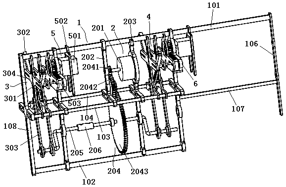
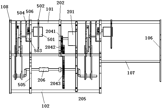
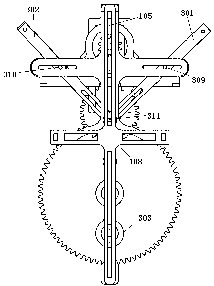
[0043] Such as Figure 1-12 As shown, a carbon fiber flapping wing aircraft that is easy to disassemble includes a frame 1, a drive unit 2, a wing unit and a direction control unit; the frame 1 includes two upper and lower frameworks arranged in parallel, and the upper and lower The front ends of the two frames are plugged in and fixedly connected to the upper and lower ends of the head frame 108 by screws. The upper frame 101 is longer than the lower frame 102 and the ends are plugged in and fixedly connected with a tail rod 106; The wing module 3 and the rear flapping wing module 4, the direction control unit includes the front wing direction control module 5 and the rear wing direction control module 6; the front flapping wing module 3, the front wing direction control module 5, the drive unit 2, the rear flapping wing module The module 4 a...


PUM


Abstract

The invention discloses a carbon fiber flapping wing aircraft easy to disassemble and assemble. The carbon fiber flapping wing aircraft comprises a rack, a driving unit, a wing unit and a direction control unit; the rack comprises an upper framework and a lower framework which are arranged in parallel, the front ends of the upper framework and the lower framework are connected with the upper end and the lower end of the head support, the upper framework is longer than the lower framework, and the tail end of the upper framework is connected with a tail rod; the wing unit comprises a front flapping wing module and a rear flapping wing module, and the direction control unit comprises a front wing direction control module and a rear wing direction control module; and the front flapping wing module, the front wing direction control module, the driving unit, the rear flapping wing module and the rear wing direction control module are sequentially arranged between the upper framework and thelower framework from front to back. During assembly, the positions of all parts can be adjusted more conveniently, and the running smoothness of the whole aircraft is guaranteed; and in addition, parts can be quickly replaced under the condition of falling and breaking.

Description

technical field [0001] The invention relates to the technical field of aircraft, in particular to an easily disassembled carbon fiber flapping-wing aircraft. Background technique [0002] With the development of science, people's living standards are getting higher and higher, and the use of electronically controlled aircraft such as drones in daily life is becoming more and more common. [0003] The flapping-wing aircraft has unique advantages such as low Reynolds number, good aerodynamic performance, small size, good concealment, and easy to carry, and has great application prospects. In the military, the flapping-wing aircraft equipped with miniature cameras, bugs, bombs, detectors and other equipment can perform tasks such as investigation, eavesdropping, precise target removal, and electronic interference by using its high concealment, confusion, and maneuverability; Wing aircraft can provide real-time intelligence in hostage-taking or urban anti-terrorism, assist in s...

Claims


Application Information

Patent Timeline
Patent Type & Authority Applications(China)
IPC IPC(8): B64C33/02
CPCB64C33/02B64U10/40B64U50/19B64U2101/00
Inventor 张锐张海洋张龙旦李帅杨双武婉婉王德蕊
Owner HUAIYIN INSTITUTE OF TECHNOLOGY
Why Eureka
Try Eureka