
A kind of buried organic fertilizer biological fermentation device

A bio-fermentation and organic fertilizer technology, applied in fertilization devices, organic fertilizers, organic fertilizer equipment, etc., can solve the problems of inconvenient material extraction, material removal, and inconvenient maintenance, and achieve convenient material extraction, convenient output, and convenient maintenance Effect

Active Publication Date: 2020-10-30
荆门华牧生物科技有限公司
View PDF9 Cites 1 Cited by
  • Summary
  • Abstract
  • Description
  • Claims
  • Application Information

AI Technical Summary

Problems solved by technology

[0005] The purpose of the present invention is to provide a buried organic fertilizer bio-fermentation device to solve the problem that before and after the fermentation operation is carried out in the above-mentioned background technology, since most of the tank body itself is located below the ground, it is very troublesome to take out the material after fermentation. , the tank body contains various materials such as residues and liquids, and it is inconvenient to take materials, and after the tank body is located below the ground, its approximate height cannot be adjusted, which is not convenient for subsequent maintenance; during the fermentation process, not only the temperature needs to be kept at Within a certain range, it is necessary to stir the materials in the tank frequently to ensure full contact between the raw materials and the fermentation bacteria. However, some biological raw materials have various forms, which leads to the insufficient stirring efficiency of the existing stirring structure for the fermentation raw materials, which reduces the fermentation efficiency. efficiency problem

Method used


Image

  • A kind of buried organic fertilizer biological fermentation device
  • A kind of buried organic fertilizer biological fermentation device
  • A kind of buried organic fertilizer biological fermentation device

Examples


Embodiment Construction

[0018] The following will clearly and completely describe the technical solutions in the embodiments of the present invention with reference to the accompanying drawings in the embodiments of the present invention. Obviously, the described embodiments are only some, not all, embodiments of the present invention. Based on the embodiments of the present invention, all other embodiments obtained by persons of ordinary skill in the art without making creative efforts belong to the protection scope of the present invention.

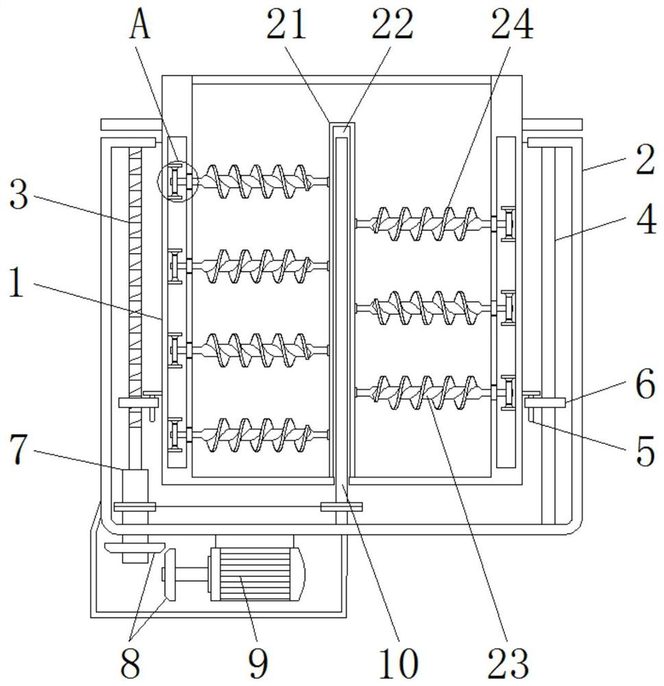
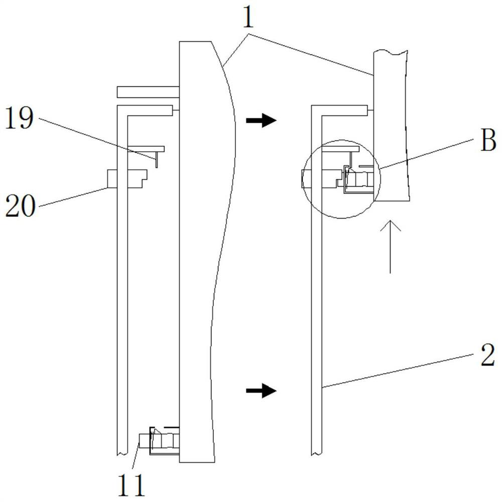
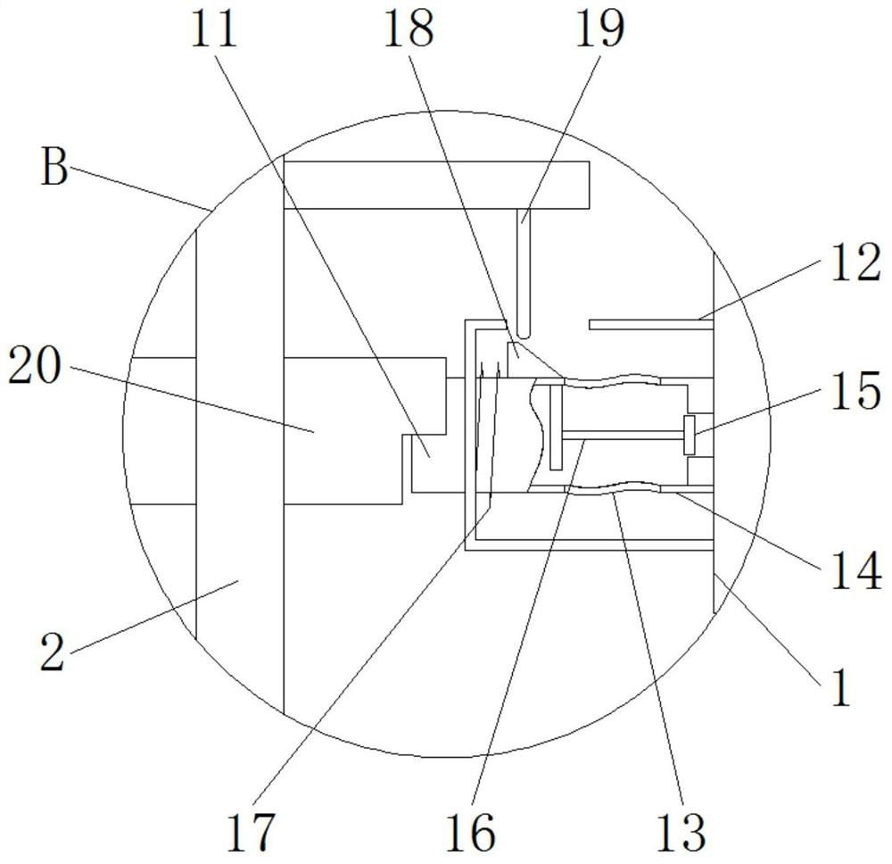
[0019] see Figure 1-6 , the present invention provides a technical solution: a buried organic fertilizer biological fermentation device, including a fermentation tank 1, an outer tank 2, a screw rod 3, a sliding rod 4, a vertical rod 5, a horizontal plate 6, a sleeve 7, Bevel teeth 8, motor 9, vertical shaft 10, first horizontal pipe 11, casing 12, hose 13, second horizontal pipe 14, valve plate 15, connecting rod 16, spring 17, guide plate 18, guide rod 19, ...


PUM


Abstract

The invention discloses a buried organic fertilizer biological fermentation device comprising a fermentation tank vertically arranged in an outer-layer tank. A first transverse pipe and a second transverse pipe which are horizontally distributed are mounted on the back surface of the bottom of the fermentation tank; a horizontally-distributed discharging pipe is installed on the side of the top ofthe outer-layer tank, a notch matching the first transverse pipe is formed in the lower portion of the inner end of the outer-layer tank, the outer diameter of the first transverse pipe matches the inner diameter of the discharging pipe. A main shaft is rotatably installed in the center of the interior of the fermentation tank, and a stirring shaft is rotatably installed on the side edge of the main shaft. According to the buried organic fertilizer biological fermentation device, on the basis of the double-layer tank body structure, the fermentation tank on the inner layer can be driven by amotor to ascend or descend; meanwhile, efficient stirring of internal materials can be achieved through power of the same motor under transmission of a corresponding structure, and when the fermentation tank rises to a certain degree, the internal space of the tank body can correspondingly communicate with the discharging pipe, so that efficient discharging of the fermented materials is facilitated.

Description

technical field [0001] The invention relates to the technical field of organic fertilizer processing, in particular to a buried organic fertilizer biological fermentation device. Background technique [0002] Organic fertilizer refers to the fertilizer obtained by using plant or animal waste through biological fermentation. It contains a lot of beneficial substances and has high nutritional value for crops. In the process of production and processing, fermenters need to be used For placed fermentation operation, due to the high temperature requirements during the fermentation process, the fermenter used for fermentation will be buried in the ground to ensure that the temperature environment outside the tank remains within a general range. However, the existing similar fermenter tanks are The following problems exist in actual use: [0003] 1. Before and after the fermentation operation, since most of the tank itself is located below the ground, it is very troublesome to tak...

Claims


Application Information

Patent Timeline
Patent Type & Authority Patents(China)
IPC IPC(8): C05F17/90C05F17/964
CPCY02W30/40
Inventor 陈婷婷
Owner 荆门华牧生物科技有限公司
Learn More