Al technical title is built by PatSnap Al team. It summarizes the technical point description of the patent document.
A wear-resistant ceramic and shaft technology, used in sliding valves, valve details, valve devices, etc., can solve the problems of wear of sealing rings and valve plates, affecting safe production, ash formation, etc., to achieve good sealing performance, long service life, Maintenance simple effect
Active Publication Date: 2022-03-04
HENAN DINGSHENG ALUMINUM CO LTD
View PDF0 Cites 0 Cited by
Summary
Abstract
Description
Claims
Application Information
AI Technical Summary
This helps you quickly interpret patents by identifying the three key elements:
Problems solved by technology
Method used
Benefits of technology
Problems solved by technology
[0002] At present, the valves used in various dust and particle conveying systems in thermal power plants, metallurgy, and chemical industries are generally made of carbon steel or wear-resistant steel. Due to the continuous erosion of powder particles, the sealing ring and valve plate are easily damaged. Abrasion, poor sealing performance and wear resistance, resulting in ash leakage, air pollution, environmental pollution, and often ash and jamming
In the end, the entire valve is scrapped, which not only increases the cost of equipment repair and maintenance, but more importantly, affects safe production.
Method used
Image
Click on the blue label to locate the original text in one second.
Reading with bidirectional positioning of images and text.
Examples
Embodiment Construction
[0021] The present invention is described in further detail below by embodiment, and embodiment is only used for illustrating the present invention, does not limit the scope of the present invention.
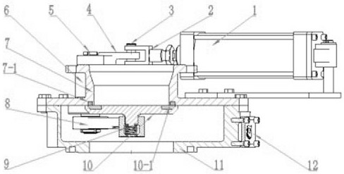
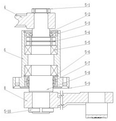
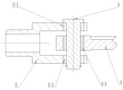
[0022] see Figure 1-3 A pneumatic wear-resistant ceramic rotary slag discharge valve shown includes a pneumatic mechanism 1, an outer rocker arm 4, a shaft assembly 5, a shaft sleeve 6, an upper valve body 7, an inner rocker arm 8, a spring seat, a valve plate 10 and a lower The valve body 11, the upper valve body 7 and the lower valve body 11 are fixed and sealed, and the pneumatic mechanism 1 is connected with the outer rocker arm 4. The preferred pneumatic mechanism 1 is installed on the outside of the upper valve body 7 through the cylinder bracket; the outer rocker arm 4 The shaft assembly 5 is connected to the inner rocker arm 8, and the inner rocker arm 8 is connected to the valve plate 10 through a spring seat. The shaft assembly 5 includes a shaft 5-8, and the upper en...
PUM
Abstract
The invention relates to the technical field of valve equipment, in particular to a pneumatic wear-resistant ceramic rotary slag discharge valve, which includes a pneumatic mechanism, an outer rocker arm, a rotating shaft assembly, a rotating shaft sleeve, an upper valve body, an inner rocker arm, a spring seat, a valve plate and a lower valve body. The valve body, the upper valve body and the lower valve body are fixed and sealed, the pneumatic mechanism is connected with the outer rocker arm, the outer rocker arm is connected with the inner rocker arm through the rotating shaft assembly, and the inner rocker arm is connected with the valve plate through the spring seat; the rotating shaft The assembly includes a rotating shaft, the upper end of which is fixedly connected to the outer rocker arm, the rotating shaft is arranged in the rotating shaft sleeve, and the rotating shaft sleeve is arranged on the upper valve body; the lower end of the rotating shaft is fixedly connected to one end of the inner rocker arm; the other end of the inner rocker arm It is fixedly connected with the spring seat, and the bottom of the spring seat is provided with a mold spring, and the valve plate is connected with the spring seat through the mold spring. The invention has reasonable structure, wear resistance, high heat resistance, and long service life. Power plant, metallurgy, medicine, chemical industry and other dust and particle conveying systems.
Description
technical field [0001] The invention relates to the technical field of valve equipment, in particular to a pneumatic wear-resistant ceramic rotary slag discharge valve. Background technique [0002] At present, the valves used in various dust and particle conveying systems in thermal power plants, metallurgy, and chemical industries are generally made of carbon steel or wear-resistant steel. Due to the continuous erosion of powder particles, the sealing ring and valve plate are easily damaged. Abrasion, poor sealing performance and wear resistance, resulting in ash leakage, air pollution, environmental pollution, and often ash and jamming. Finally, the entire valve is scrapped, which not only increases the maintenance cost of equipment, but more importantly, affects safe production. Contents of the invention [0003] In order to solve the problems in the prior art, the invention provides a pneumatic wear-resistant ceramic rotary slag discharge valve with reasonable struct...
Claims
Application Information
Patent Timeline
Application Date:The date an application was filed.
Publication Date:The date a patent or application was officially published.
First Publication Date:The earliest publication date of a patent with the same application number.
Issue Date:Publication date of the patent grant document.
PCT Entry Date:The Entry date of PCT National Phase.
Estimated Expiry Date:The statutory expiry date of a patent right according to the Patent Law, and it is the longest term of protection that the patent right can achieve without the termination of the patent right due to other reasons(Term extension factor has been taken into account ).
Invalid Date:Actual expiry date is based on effective date or publication date of legal transaction data of invalid patent.