
Optical lens group, camera module and terminal

An optical mirror and optical system technology, applied in optics, optical components, instruments, etc., can solve problems such as inability to accurately control the air gap, low imaging quality of the camera lens, and difficulty in grasping the size of the edge area, so as to reduce poor imaging performance , Improve stability and reliability, and reduce production cost loss

Pending Publication Date: 2020-06-26
JIANGXI JINGCHAO OPTICAL CO LTD
View PDF0 Cites 3 Cited by
  • Summary
  • Abstract
  • Description
  • Claims
  • Application Information

AI Technical Summary

Problems solved by technology

[0002] At present, based on the three-element and four-element camera lens, it can no longer meet the higher-level imaging quality requirements, and the lens of the camera lens has begun to develop in the direction of more lenses. Among them, the overall length of the comprehensive camera lens, manufacturing process , production cost and overall yield and other factors have an impact on the camera lens, the camera device will be better than the camera lens with five optical elements
[0003] With the gradual increase in the number of optical lenses in the camera lens, it is difficult to grasp the size of the edge area of ​​each lens, and there will be a problem that the air gap between two adjacent lenses cannot be accurately controlled, which will lead to the poor imaging quality of the entire camera lens. Not high, and it will increase the defect rate of the lens during the lens production process

Method used


Image

  • Optical lens group, camera module and terminal
  • Optical lens group, camera module and terminal
  • Optical lens group, camera module and terminal

Examples


Embodiment 1

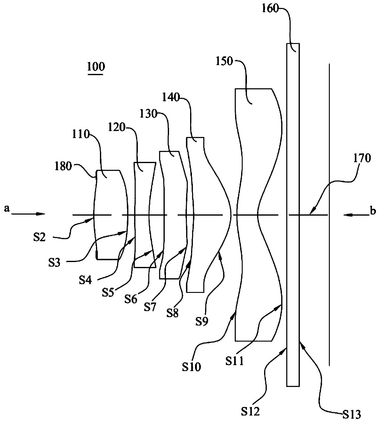
[0101] For a schematic structural diagram of the imaging optical mirror group 100 of the embodiment of the present application, see figure 1 , the optical lens group 100 includes a diaphragm 180 (attached to the object side of the first lens 110 ), a first lens 110 , a second lens 120 , and a third lens 130 arranged in sequence from the object plane a to the image plane b along the optical axis 170 , the fourth lens 140, the fifth lens 150 and the infrared filter 160.

[0102] The first lens 110 has a positive refractive power, the object side of the first lens 110 at the optical axis 170 is a convex surface, and the image side of the first lens 110 at the optical axis 170 is a convex surface. The object side of the first lens 110 at the circumference is convex, and the image side of the first lens 110 at the circumference is convex.

[0103] The second lens 120 has a negative refractive power, the object side of the second lens 120 at the optical axis 170 is convex, and the ...

Embodiment 2

[0130] For a schematic structural diagram of the imaging optical mirror group 100 of the embodiment of the present application, see Figure 5 , the optical lens group 100 includes a diaphragm 180 (attached to the object side of the first lens 110 ), a first lens 110 , a second lens 120 , and a third lens 130 arranged in sequence from the object plane a to the image plane b along the optical axis 170 , the fourth lens 140, the fifth lens 150 and the infrared filter 160.

[0131] The first lens 110 has a positive refractive power, the object side of the first lens 110 at the optical axis 170 is a convex surface, and the image side of the first lens 110 at the optical axis 170 is a convex surface. The object side of the first lens 110 at the circumference is convex, and the image side of the first lens 110 at the circumference is convex.

[0132] The second lens 120 has a negative refractive power, the object side of the second lens 120 at the optical axis 170 is convex, and the...

Embodiment 3

[0159] For a schematic structural diagram of the imaging optical mirror group 100 of the embodiment of the present application, see Figure 9 , the optical lens group 100 includes a stop 180 (attached to the object side of the first lens 110 ), a first lens 110 , a second lens 120 , and a third lens 130 arranged in sequence from the object plane a to the image plane b along the optical axis 170 , the fourth lens 140, the fifth lens 150 and the infrared filter 160.

[0160] The first lens 110 has a positive refractive power, the object side of the first lens 110 at the optical axis 170 is a convex surface, and the image side of the first lens 110 at the optical axis 170 is a concave surface. The object side of the first lens 110 at the circumference is convex, and the image side of the first lens 110 at the circumference is convex.

[0161] The second lens 120 has a negative refractive power, the object side of the second lens 120 at the optical axis 170 is convex, and the ima...


PUM

PropertyMeasurementUnit
Wavelengthaaaaaaaaaa

Abstract

The invention discloses an optical lens group, a camera module and a terminal. The optical lens group comprises a first lens, a second lens, a third lens, a fourth lens and a fifth lens which are sequentially arranged from an object plane to an image plane along an optical axis, the first lens has positive meandering force. The image side surface of the second lens at the optical axis is a concave surface; the image side surface of the fourth lens at the optical axis is a convex surface; the image side surface of the fifth lens at the optical axis is a concave surface; the vector height of the object side surface of the first lens is SAGF11; the vector height of the image side surface of the first lens is SAGF12, the air interval between the first lens and the second lens at the maximum effective diameter is ET12, and SAGF11, SAGF12 and ET12 satisfy the following conditional expression: 0 < = (| SAGF11 | + | SAGF12 |) / ET12 < = 5. Through the arrangement, the injection molding yield ofthe lens can be improved, and the influence of quality fluctuation caused by the molding tolerance of the lens and the lens cone and the assembly process on the imaging performance is reduced, so that the production stability and the comprehensive yield are improved on the premise of ensuring the imaging quality, and the product profit is improved.

Description

technical field [0001] The present application relates to the technical field of optical imaging, in particular to an optical lens group, a camera module and a terminal. Background technique [0002] At present, based on the three-element and four-element camera lens, it can no longer meet the higher-level imaging quality requirements, and the lens of the camera lens has begun to develop in the direction of more lenses. Among them, the overall length of the comprehensive camera lens, manufacturing process , production cost and overall yield rate and other factors have an impact on the camera lens, the camera device will be better than choosing a camera lens composed of five optical elements. [0003] With the gradual increase in the number of optical lenses in the camera lens, it is difficult to grasp the size of the edge area of ​​each lens, and there will be a problem that the air gap between two adjacent lenses cannot be accurately controlled, which will lead to the poor ...

Claims


Application Information

Patent Timeline
IPC IPC(8): G02B13/18G02B13/00
CPCG02B13/0045G02B13/18
Inventor 王妮妮刘彬彬李明邹海荣
Owner JIANGXI JINGCHAO OPTICAL CO LTD
Learn More