Method for forming flange at any position of pipe in progressive thickeningmode
A flange and pipe technology, which is applied in the field of progressively thickening forming flanges at any position in the axial direction of the pipe, can solve problems such as increasing the amount of deformation, and achieve the effect of preventing distortion or filling dissatisfaction, improving the forming limit and improving the forming efficiency.
- Summary
- Abstract
- Description
- Claims
- Application Information
AI Technical Summary
Problems solved by technology
Method used
Image
Examples
Embodiment 1
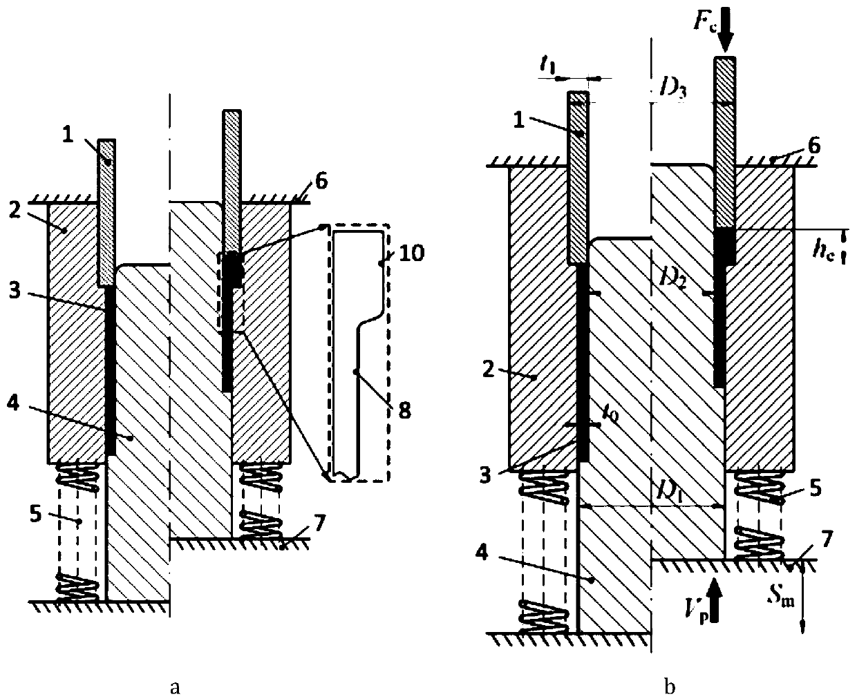
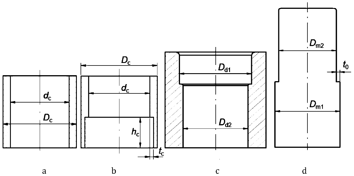
[0024] Such as figure 1 , image 3 and Figure 4 As shown, in this embodiment, the flange thickening is formed at the end of the pipe fitting 3, and the specific position is the upper nozzle h of the pipe fitting 3 e Section, specifically provide constant pressure F through external hydraulic equipment c , and use the compression molding device with workbench 6, 7 to carry out upsetting processing on the pipe fitting 3, and set the stroke S of the workbench according to the size of the flange to be formed m , so that the table moves at a constant speed V p Drive the compression molding device, as the mandrel 4 goes up, the pipe fitting 3 is gradually squeezed into the forming cavity from the positioning cavity, and the side wall of the pipe fitting 3 is gradually thickened until the stroke ends to form a flange.
[0025] The compression molding device includes: a reverse top punch 1, a die 2 and a mandrel 4, wherein: the reverse top punch 1 is slidably matched with the die...
Embodiment 2
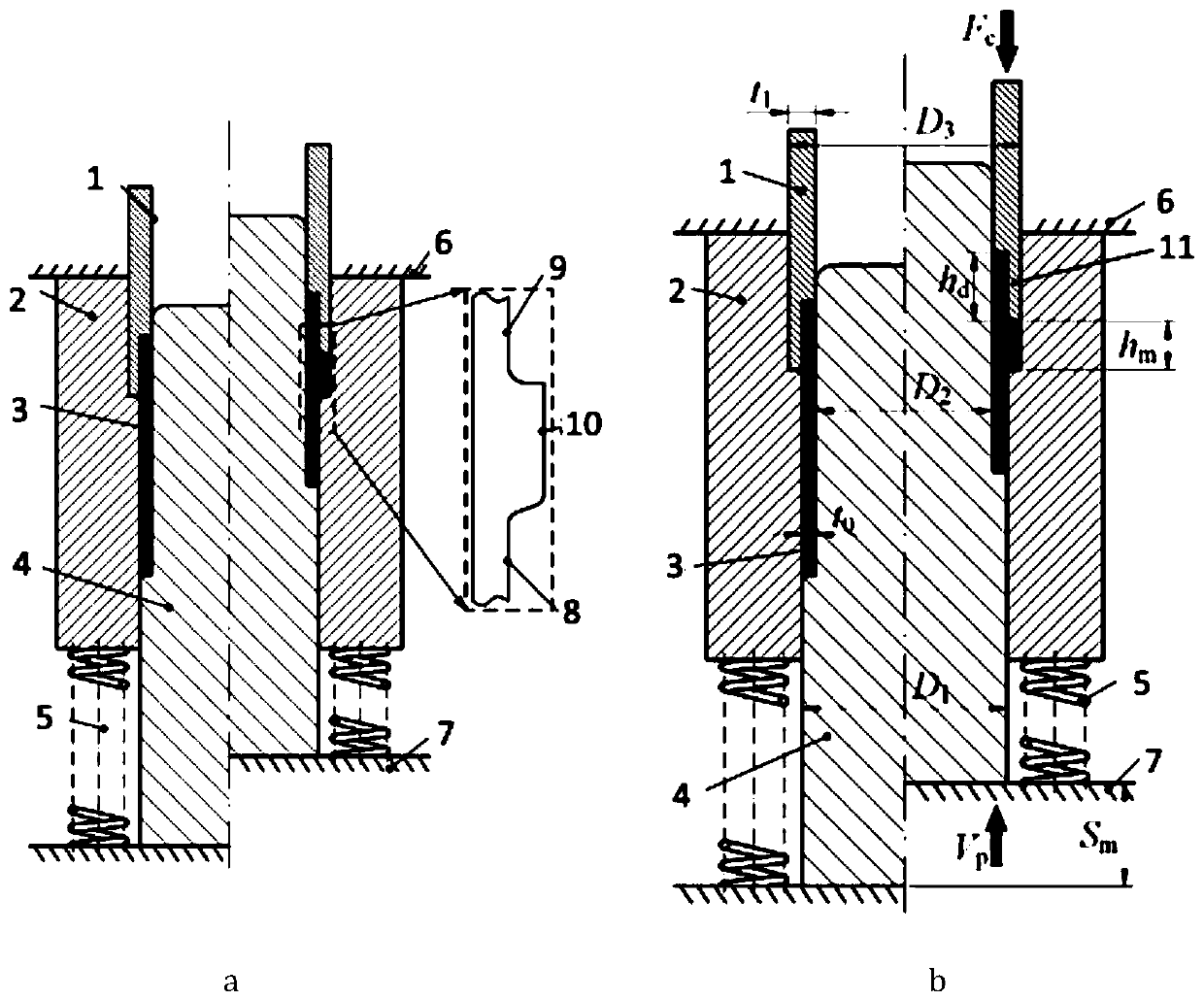
[0034] Such as figure 2 , image 3 and Figure 4 As shown, in this embodiment, the flange thickening is formed in the middle of the pipe fitting 3, and the specific thickening position is h from the upper nozzle of the pipe fitting 3 d place. Compared with Embodiment 1, the reverse punch 1 of this embodiment has added a positioning structure 11, so the closed cavity where the pipe fittings are located can be divided into three parts. The specific conditions are as follows:
[0035] The reverse top punch 1 with the positioning structure is as image 3 As shown in b, the height of the positioning structure is h c and satisfy h c =h d , with a width of t c and satisfy t c = t 0 .
[0036] The closed cavity includes in turn: a forming cavity 10, a protective cavity 8 and a positioning cavity 9, wherein: the diameter of the forming cavity 10 is the same as the outer diameter of the flange, and the diameter of the protective cavity 8 is the same as the outer diameter of t...
PUM
 Abstract
Description
Claims
Application Information
 - R&D
- Intellectual Property
- Life Sciences
- Materials
- Tech Scout
- Unparalleled Data Quality
- Higher Quality Content
- 60% Fewer Hallucinations
Browse by: Latest US Patents, China's latest patents, Technical Efficacy Thesaurus, Application Domain, Technology Topic, Popular Technical Reports.
© 2025 PatSnap. All rights reserved.Legal|Privacy policy|Modern Slavery Act Transparency Statement|Sitemap|About US| Contact US: help@patsnap.com


