Hot metal ladle slagging-off control system, slagging-off machine and hot metal ladle automatic slagging-off control method

A control system and control method technology, applied in the field of iron and steel metallurgy industry, can solve problems such as insufficient reliability and low efficiency of slag removal, and achieve the effects of improving the removal rate, reducing the time of slag removal, and reducing the sulfur content rate

Inactive Publication Date: 2020-06-30
HENGYANG RAMON SCI & TECH CO LTD
View PDF8 Cites 17 Cited by
  • Summary
  • Abstract
  • Description
  • Claims
  • Application Information

AI Technical Summary

Problems solved by technology

[0004] The technical problem to be solved by the present invention is to provide a slag removal control system and automatic slag removal control method for molten iron tanks, so as to solve the problems of insufficient visibility and reliability of the slag removal process and low efficiency of slag removal in the prior art technical problem

Method used


Image

  • Hot metal ladle slagging-off control system, slagging-off machine and hot metal ladle automatic slagging-off control method
  • Hot metal ladle slagging-off control system, slagging-off machine and hot metal ladle automatic slagging-off control method
  • Hot metal ladle slagging-off control system, slagging-off machine and hot metal ladle automatic slagging-off control method

Examples


Embodiment Construction

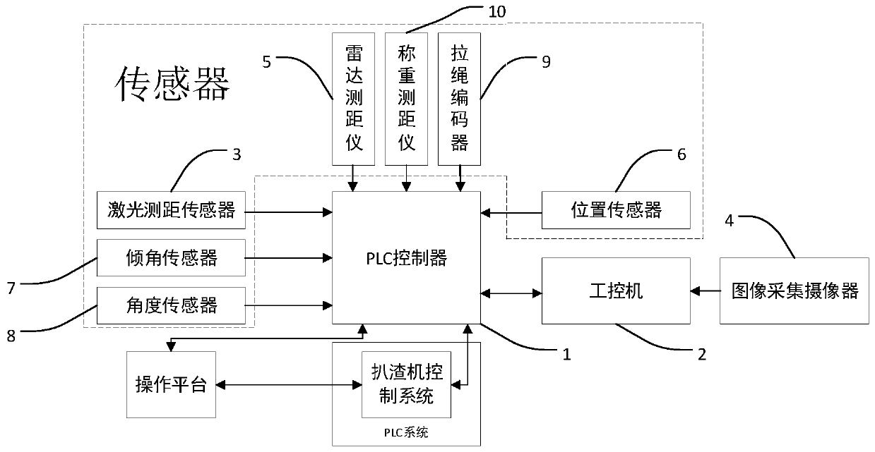
[0030] The molten iron tank slag removal control system of the present invention is constructed based on the comprehensive use of technologies such as image recognition, laser ranging, radar ranging, PLC control, position and angle detection, and path planning models. The slag removal system controls each part to perform corresponding actions, and cooperates with each other to realize the automatic slag removal function. The reduction of manpower, the reduction of molten iron loss and the improvement of slag removal efficiency in the process of steelmaking are realized.

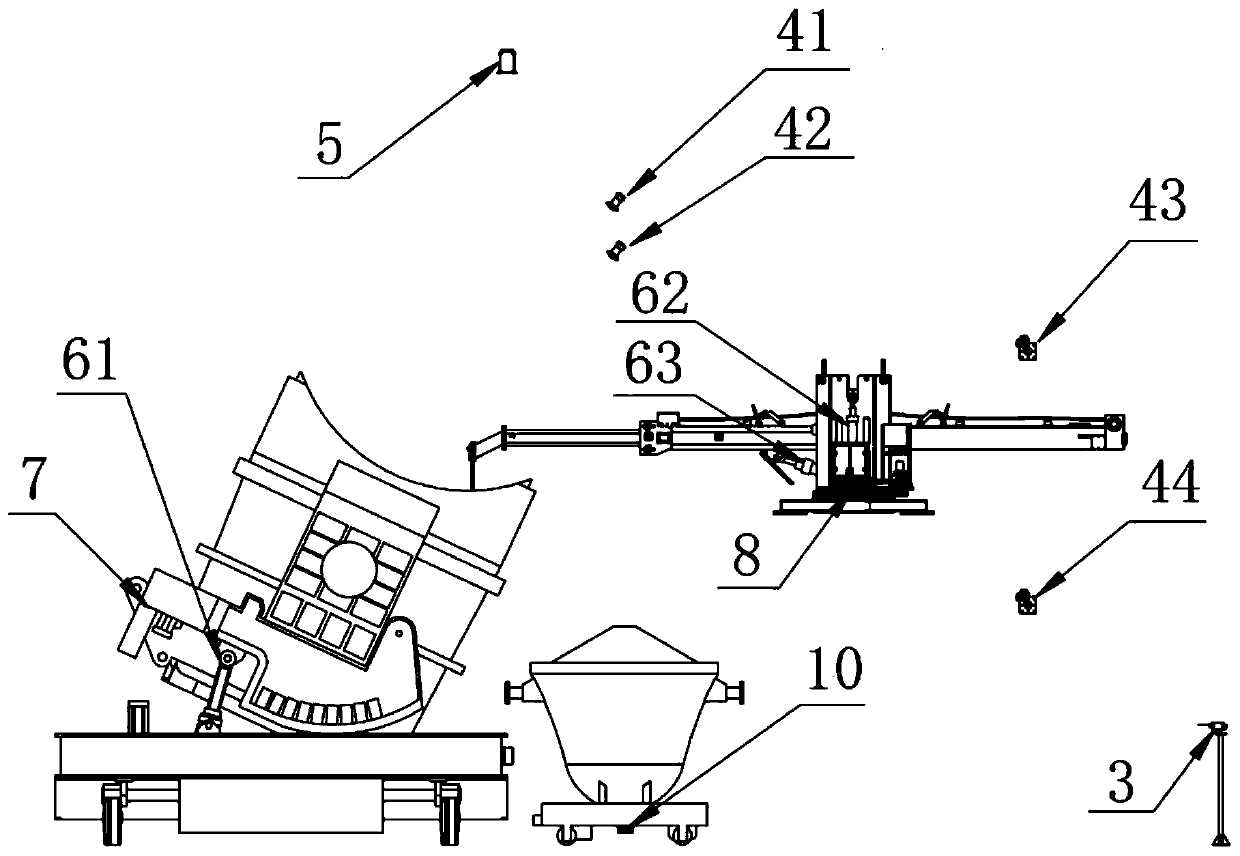
[0031] A control system for removing slag from molten iron tanks provided by the present invention, see figure 1 and figure 2, including image acquisition camera 4, laser ranging sensor 3, radar rangefinder 5, position sensor 6, inclination sensor 7, rope encoder 9, load cell 10, PLC controller 1 and industrial computer 2:

[0032] The working steps of the molten iron tank slag removal control system are a...


PUM


Abstract

The invention provides a hot metal ladle slagging-off control system. The hot metal ladle slagging-off control system comprises a laser distance measuring sensor, an image acquisition camera, a radardistance measuring instrument, a first position sensor, a tilt angle sensor, a pull rope encoder, a angle sensor, a second position sensor, a first weighing sensor, a first image acquisition camera, asecond image acquisition camera, a second weighing sensor, a cabinet and automatic slagging-off control software, wherein the laser distance measuring sensor is arranged on one side of a running track of a hot metal ladle car and is connected with a PLC, the image acquisition camera is arranged on the front surface of a dust hood above a hot metal ladle, the radar distance measuring instrument isarranged on the back surface of the dust hood above the hot metal ladle and is connected with the PLC, the first position sensor is mounted in an oil cylinder for controlling tilting action of the hot metal ladle and is in control connection with the PLC, the tilt angle sensor is mounted on the hot metal ladle car and is connected with the PLC, the pull rope encoder, the angle sensor and the second position sensor are mounted on a slagging-off machine and are connected with the PLC, the second position sensor can control the oil cylinder, the first weighing sensor is installed at the bottom of a slag basin transport vehicle and is connected with the PLC, the first image acquisition camera is installed on a platform of the slagging-off machine, the second image acquisition camera is installed above a slag receiving position of a slag basin, the second weighing sensor is installed at the bottom of the slag basin, and the cabinet comprises the PLC and an industrial personal computer.

Description

technical field [0001] The invention belongs to the field of iron and steel metallurgy industry, and in particular relates to a control system for removing slag from a molten iron tank, a slag remover and a control method for automatically removing slag from a molten iron tank. Background technique [0002] In the field of iron and steel metallurgy industry, steelmaking is a very important part, and the slag removal process is an important part of the steelmaking process. The maturity of the slag removal process is not only related to the quality of downstream molten steel, but also related to the cost and benefit of iron and steel enterprises. In the original period of the steelmaking industry, the slag removal process was mainly realized by manually lifting the slag removal plate. Not only was the efficiency low, the slag removal time was long, the waste of molten steel was also serious, and there was even a considerable risk of accidents. . After the appearance of the s...

Claims


Application Information

Patent Timeline
Patent Type & Authority Applications(China)
IPC IPC(8): C21C7/00B22D43/00B22D46/00
CPCB22D43/007B22D46/00C21C7/0087
Inventor 田陆田立谢卫东肖小文
Owner HENGYANG RAMON SCI & TECH CO LTD
Why Eureka
Try Eureka