Isolation assembly for partitioning of isolation area ward

A technology for isolating components and isolation areas, which is applied to building components, walls, buildings, etc., can solve the problems of poor isolation effect and simple function of isolation devices, and achieve the effect of convenient installation, good sealing and isolation effect, and simple structure

Inactive Publication Date: 2020-06-30
太和县卡巴拉医疗设备有限公司
View PDF8 Cites 3 Cited by
  • Summary
  • Abstract
  • Description
  • Claims
  • Application Information

AI Technical Summary

Problems solved by technology

[0007] The purpose of the present invention is to provide an isolation assembly for ward partitioning in an isolation area. The isolation curtain wall is formed inside the ward according to the bed positions through the exhaust assembly, and small isolation areas are formed inside the ward, and the polluted air in each isolation area is passed through. The ventilation components are exhausted, which solves the problems of poor function, poor isolation effect and space occupation of the existing internal isolation device in the ward

Method used


Image

  • Isolation assembly for partitioning of isolation area ward
  • Isolation assembly for partitioning of isolation area ward
  • Isolation assembly for partitioning of isolation area ward

Examples


Embodiment 1

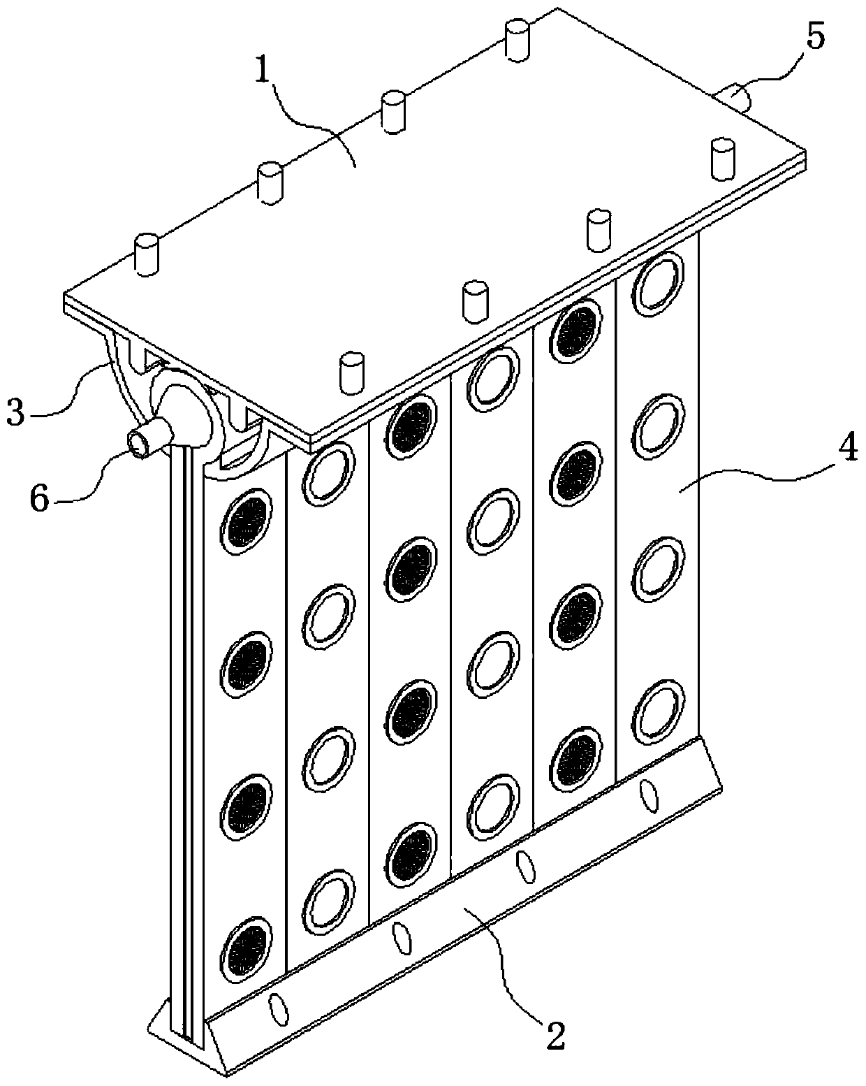
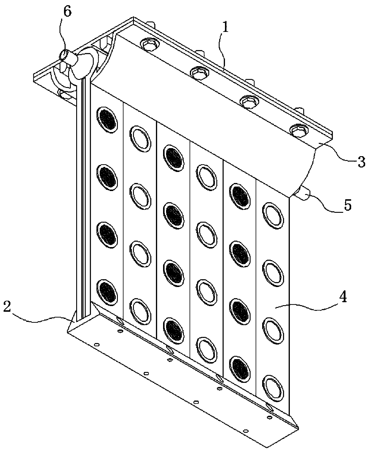
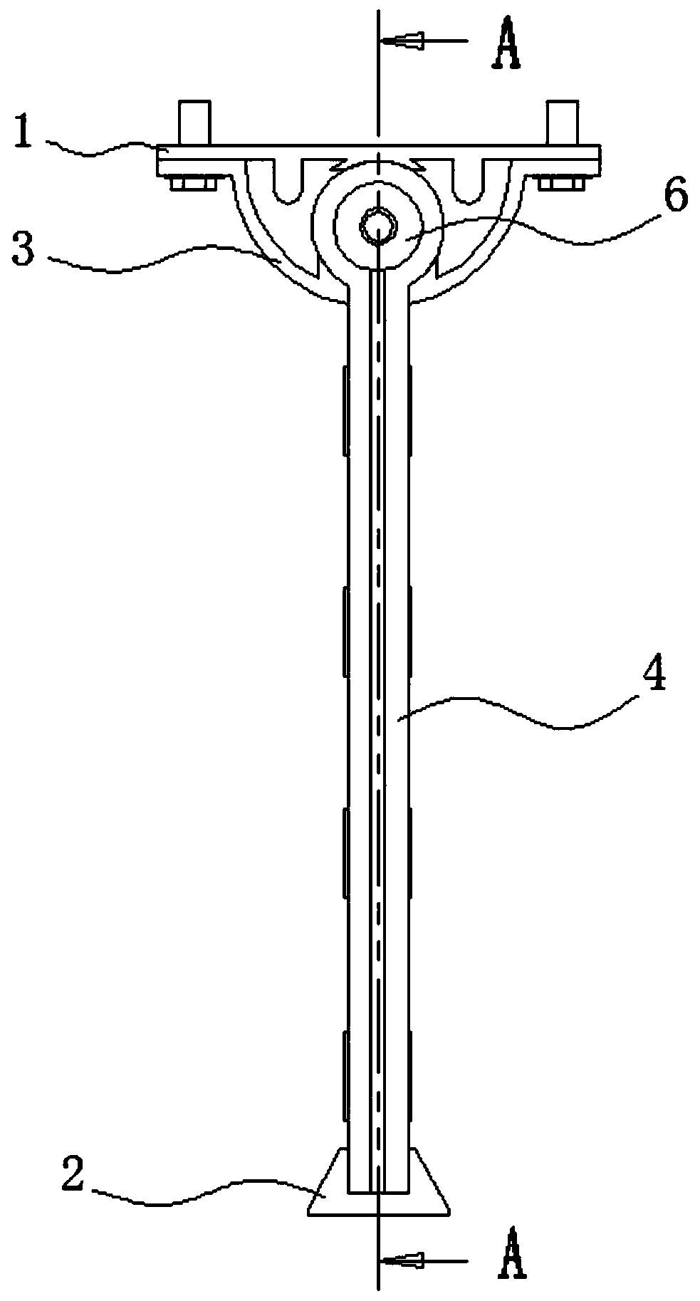
[0042] see Figure 1-14 As shown, the present invention is an isolation assembly for ward partitioning in an isolation area, including a top plate 1 and a limiting slot 2, two clamping plates 3 are fixed on the lower surface of the top plate 1 by bolts, and a A plurality of ventilation components 4 connected to each other, the bottom of the ventilation component 4 is clamped with the limiting slot 2, and the width of the ventilation component 4 is determined proportionally according to the length of the top plate 1 and the limiting slot 2.

[0043] The top plate 1, the limit card slot 2, the card plate 3 and the exhaust assembly 4 are used in combination to complete the partition. The structure is simple, the function is obvious, the environmental requirements are low, and it is suitable for a large number of installations in emergency situations, and the installation efficiency is high.

[0044] In order to ensure the stability of the connection, the sealing of the connection...

Embodiment 2

[0056] see Figure 15 As shown, based on the isolation assembly described in Embodiment 1 for partitioning of isolation areas and wards, when in use, the top plate 1 can also be installed with glue when it is installed with the ceiling. holes to reduce damage to the building. After the components are installed according to the specific arrangement in the ward, the medical personnel adjust the positions of the air filter plug 405 and the sealing plug 406 on the partition curtain 402 according to the actual needs. Figure 15 As shown, different ventilation positions can be adjusted to improve air circulation efficiency and enhance the comfort of patients in the compartment.


PUM


Abstract

The invention discloses an isolation assembly for partitioning of an isolation area ward, and relates to the technical field of isolation equipment. The isolation assembly comprises a top plate and alimiting clamping groove, two clamping plates are fixed to the lower surface of the top plate through bolts, a plurality of air extraction assemblies communicating with one another are connected between the two clamping plates in a clamped manner, and the bottoms of the air extraction assemblies are connected with the limiting clamping groove in a clamped manner; each air extraction assembly comprises an air guide duct matched with the clamping plates, and a separation curtain is fixed to the peripheral surface of each air guide duct; and a diversion cavity communicating with an inner cavity of the corresponding air guide duct is formed in each separation curtain, and air inlet holes are formed in the front surface and the rear surface of each separation curtain. By arranging the isolationassembly for partitioning in the isolation area ward and extracting waste gas in each small isolation zone, indoor contaminated gas is prevented from circulating, the problem of cross infection in the same ward is reduced, the isolation effect is improved, and the risk of cross infection is lowered.

Description

technical field [0001] The invention belongs to the technical field of isolation equipment, and in particular relates to an isolation assembly used for partitioning wards in an isolation area. Background technique [0002] With the progress of society and the development of economy, my country's medical industry is advancing by leaps and bounds. People are paying more and more attention to medical safety and medical security. The probability of the spread of infectious germs has become the main research direction of doctors, and the demand for anti-infection isolation devices in infection departments is also increasing. [0003] Most of the isolation devices used in infection departments today have simple functions, poor isolation effect and large space occupation, which is inconvenient to install and use. Usually, an air purification device is installed in a ward to purify the air in the ward. However, when medical resources are tight, multiple patients are placed in the sa...

Claims


Application Information

Patent Timeline
Patent Type & Authority Applications(China)
IPC IPC(8): E04B2/74E04B2/82
CPCE04B2/74E04B2/82
Inventor 张惠
Owner 太和县卡巴拉医疗设备有限公司
Why Eureka
Try Eureka