
High-thrust piezoelectric linear actuator with self-locking function and driving method thereof

A high-thrust, actuator technology, applied in piezoelectric effect/electrostrictive or magnetostrictive motors, generators/motors, electrical components, etc., which can solve the difficulty of miniaturization and integration of actuators , The actuator has problems such as poor motion stability and small load capacity, and achieves the effect of simple structure, reduced friction, and improved driving force.

Pending Publication Date: 2020-06-30
TIANJIN UNIV OF TECH & EDUCATION TEACHER DEV CENT OF CHINA VOCATIONAL TRAINING & GUIDANCE +1
View PDF0 Cites 0 Cited by
  • Summary
  • Abstract
  • Description
  • Claims
  • Application Information

AI Technical Summary

Problems solved by technology

[0002] Piezoelectric actuators mainly include: (1) Signal-controlled inertial piezoelectric actuators, whose driving principle is to use asymmetrical drive signals as the power source and match the symmetrical friction force in the forward and backward directions to drive, but A complex and precise signal control system is required in the resume, which brings certain difficulties to the miniaturization and integration of the whole actuator; (2) friction control inertial piezoelectric precision actuator, its driving principle is to use symmetrical drive The driving force generated by the joint action of the signal and the mechanical clamping structure is used as the power source, and the driving is realized through the asymmetric friction force in the forward and backward directions, but the friction force is nonlinear, due to the condition of the contact surface, aging, temperature, wear and Processing and assembly errors will affect the actuator, resulting in poor motion stability, low resolution, and small load capacity of the actuator

Method used


Image

  • High-thrust piezoelectric linear actuator with self-locking function and driving method thereof
  • High-thrust piezoelectric linear actuator with self-locking function and driving method thereof
  • High-thrust piezoelectric linear actuator with self-locking function and driving method thereof

Examples


Embodiment Construction

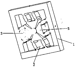
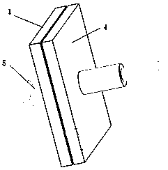
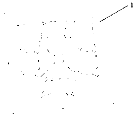
[0016] attached Figure 1-3 It is a specific embodiment of the present invention. The invention is a piezoelectric linear actuator with a large thrust and self-locking function, including a drive plate 1, a piezoelectric ceramic driver 2, a threaded push rod 3 and an end cover 4, and the drive plate 1 is provided with a plurality of drive hinges 5. A piezoelectric ceramic driver 2 is provided on the driving hinge 5 , and an end cover 4 is provided on one side of the driving disc 1 , and a threaded push rod 3 runs through the driving disc 1 and the end cover 4 .

[0017] Further, four drive hinges 5 are arranged symmetrically on the drive plate 1 , and the top ends of the drive hinges 5 are provided with threads that cooperate with the threaded push rods 3 .

[0018] Further, the threaded push rod 3 is a ball screw with a thread at one end.

[0019] Further, the outer profile of one end of the threaded push rod 3 is T-shaped.

[0020] A driving method of a piezoelectric line...


PUM


Abstract

The invention belongs to the technical field of piezoelectric actuators, and particularly relates to a high-thrust piezoelectric linear actuator with a self-locking function and a driving method thereof. According to the driving method of the high-thrust piezoelectric linear actuator with the self-locking function, pre-tightening of the piezoelectric ceramic actuator is adjusted through the pre-tightening bolt on the piezoelectric ceramic actuator; alternate driving of the two pairs of piezoelectric ceramics is achieved through voltage driving of asymmetric triangular waves, rotation of the threaded push rod is converted into front-back movement through the guiding effect of the threaded push rod, and meanwhile the threaded push rod with threads achieves the self-locking function through the T-shaped end. The beneficial effects are that the structure is simple, the four piezoelectric ceramic drivers effectively improve the driving force, the alternate driving of the two pairs of piezoelectric ceramic drivers can improve the movement speed, the threaded push rod adopts the roller screw, the guide effect can significantly reduce the friction force, improve the response resolution andimprove the response speed, and the threaded push rod has a self-locking function.

Description

technical field [0001] The invention belongs to the technical field of piezoelectric actuators, and in particular relates to a piezoelectric linear actuator with a large thrust and self-locking function and a driving method thereof. Background technique [0002] Piezoelectric actuators mainly include: (1) Signal-controlled inertial piezoelectric actuators, whose driving principle is to use asymmetrical drive signals as the power source and match the symmetrical friction force in the forward and backward directions to drive, but A complex and precise signal control system is required in the resume, which brings certain difficulties to the miniaturization and integration of the whole actuator; (2) friction control inertial piezoelectric precision actuator, its driving principle is to use symmetrical drive The driving force generated by the joint action of the signal and the mechanical clamping structure is used as the power source, and the driving is realized through the asymm...

Claims


Application Information

Patent Timeline
Patent Type & Authority Applications(China)
IPC IPC(8): H02N2/02H02N2/04H02N2/06
CPCH02N2/025H02N2/04H02N2/06
Inventor 崔良玉胡高峰韩建鑫靳刚李占杰贾静须颖
Owner TIANJIN UNIV OF TECH & EDUCATION TEACHER DEV CENT OF CHINA VOCATIONAL TRAINING & GUIDANCE
Learn More