

Collecting and separating assembly device for fish eggs and collecting method
A technology for separating components and fish eggs, which is applied in solid separation, wet separation, chemical instruments and methods, etc., can solve the problem of low efficiency, and achieve the effect of improving survivability and facilitating ecological analysis.
- Summary
- Abstract
- Description
- Claims
- Application Information
AI Technical Summary
Problems solved by technology
Method used
Image

Examples
Embodiment 1
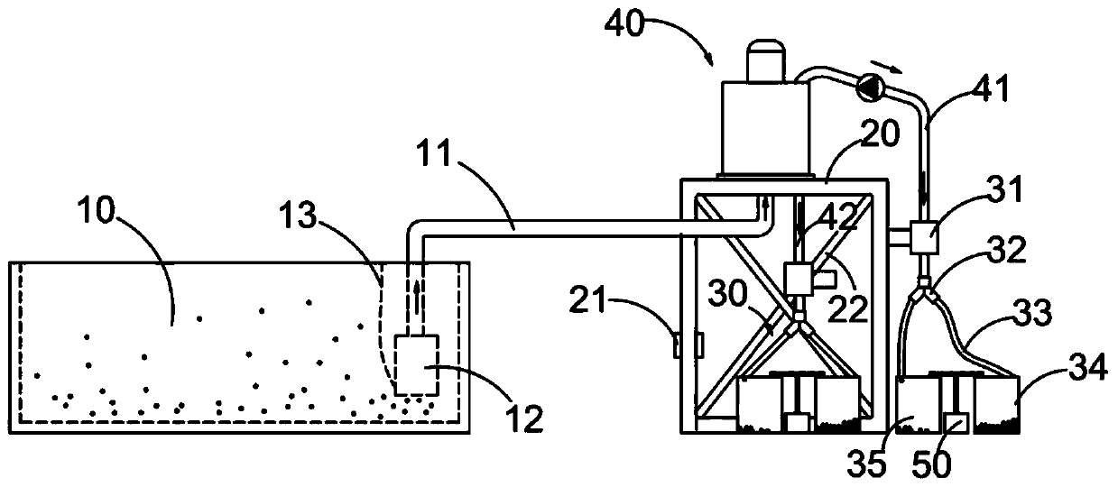
[0048] see figure 1 , 2 , 5-11, a collection and separation component device for fish eggs, comprising:
[0049] Spawning pool 10, in the spawning pool 10, at least one egg retrieval pump 12 is hoisted through the depth adjustment member 13 to set at least one egg retrieval platform 20 on the side of the spawning pool 10,
[0050] The ovum separation assembly 40 is arranged on the ovum retrieval platform 20 and connected to the ovum retrieval pump 12 through the ovum retrieval tube 11,
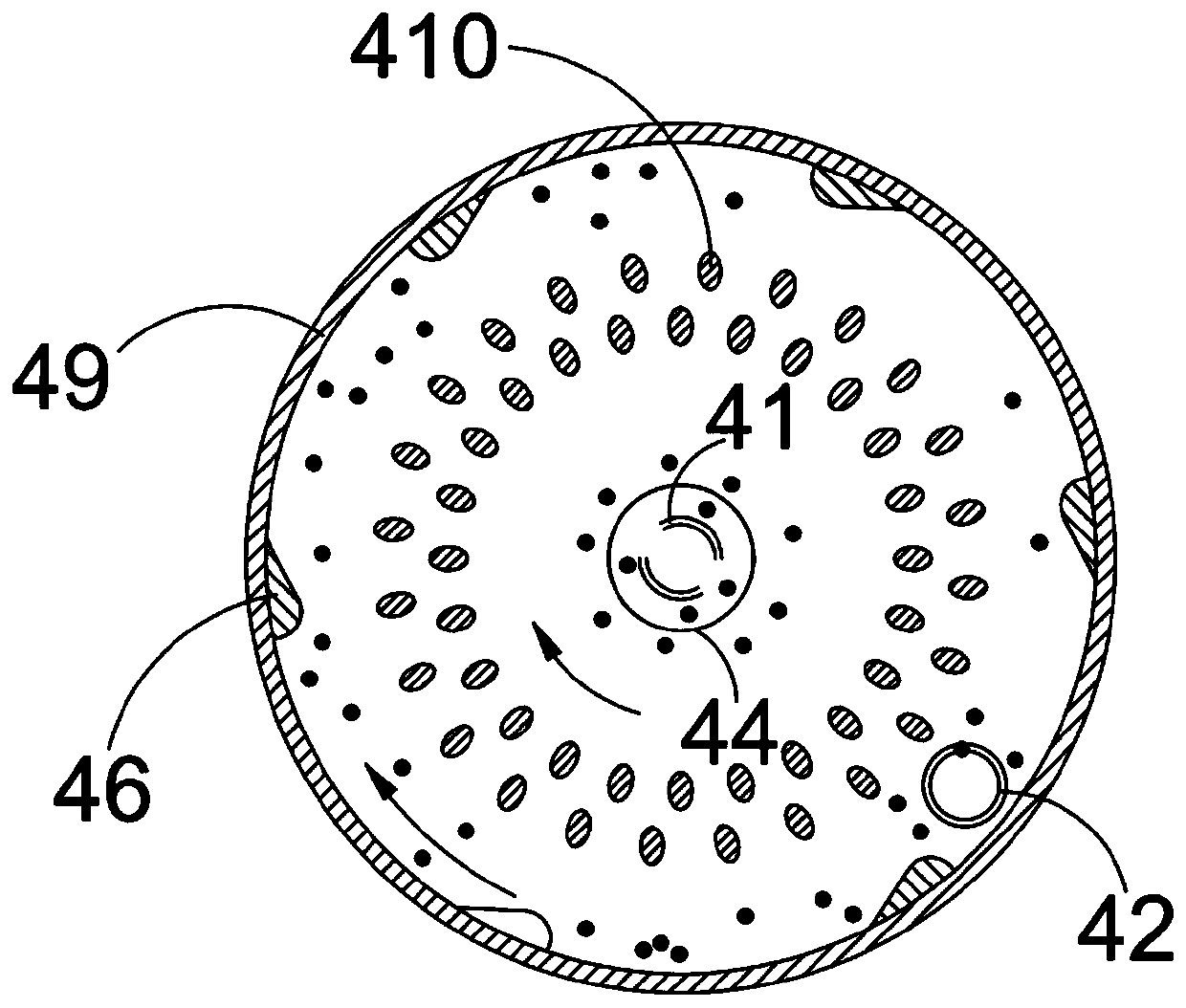
[0051] Wherein, egg separating assembly 40 comprises cylindrical egg separating shell 49, and separating egg shell 49 is fixedly arranged on the egg picking stage 20 with the axis perpendicular to the horizontal plane, and separating egg shell 49 bottom circular cylinders The center is provided with an egg inlet 44 and is connected to the egg extraction pump 12 through the egg extraction tube 11. The circular cylindrical surface at the bottom of the egg separation shell 49 is also connected ...
Embodiment 2
[0065] see Figure 12 As shown, the method for collecting fish roe using the collection and separation component device of fish roe, the steps are as follows:
[0066] -collect fish roe in the pond with ovum extraction pump 12;
[0067] - separating sinking fish eggs and buoyant fish eggs through the egg separation module 40 and utilizing the sinking and buoyancy of fish eggs;
[0068] - Send the separated fish eggs vertically downwards into the storage container with a transparent tube, and use a counter to count the number of fish eggs during the sending process;
[0069] - Use the optical signal transmitter 64 to irradiate the fish eggs moving downward from the transparent tube, receive the optical signal irradiating the fish eggs through the optical signal receiver 61 and feed back the acquired data to the control unit 50 to judge the activity of the fish eggs, and the control unit 50 calculates the activity of the eggs The body light transmittance is used to judge the e...
Embodiment 3
[0075] Fish egg separation test:
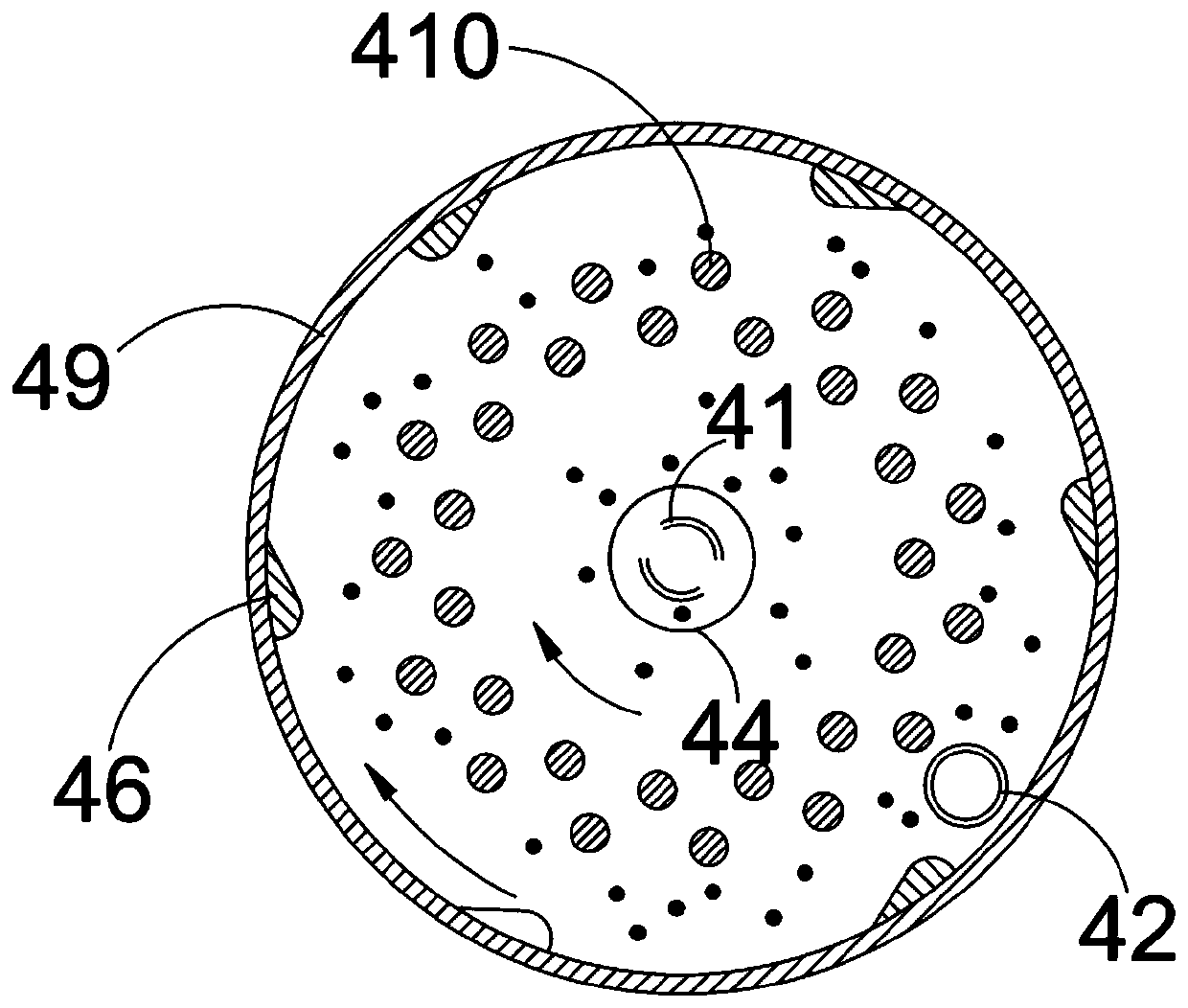
[0076] Separation group 1, separation group 2, and separation group 3 are respectively set up to carry out separation tests on fish eggs containing sinking eggs and floating eggs. The fish eggs separated by each group are 10,000 in total, and the sinking eggs and floating eggs are each 5,000. Separation groups 1-3 all adopt 40 pairs of fish roe separation work of the ovum separation assembly among the embodiment 1, wherein separation group 1 uses such as figure 2 The ovum separator 410 in the separation group 2 is used as image 3 Terminal ovum separation divider 410, separation group 3 using as image 3 Split the ovum dividing plate 410 in the middle.
[0077] The ovum separation driver 48 adopts the rotating speed of 20r / min (flow velocity is 0.1 ± 0.05m / s) to carry out the ovum separation work, and the result of counting the time spent by each separation component ovum is as follows: Figure 13As shown, and the egg separation accuracy ...
PUM
 Abstract
Description
Claims
Application Information