Mechanical arm control system achieving positioning through vision

A control system and visual positioning technology, applied in the field of intelligent manipulators, can solve problems such as difficult positioning of manipulators, achieve the effects of enhancing interactivity, saving costs, and facilitating viewing and analysis

Pending Publication Date: 2020-07-03
上海锵玫人工智能科技有限公司
View PDF5 Cites 10 Cited by
  • Summary
  • Abstract
  • Description
  • Claims
  • Application Information

AI Technical Summary

Problems solved by technology

[0004] The purpose of the present invention is to provide a visual positioning robotic arm control system, which can solve the problem of difficult positioning of the robotic arm through the visual system; use visual image technology to enhance the interactivity with the working environment

Method used


Image

  • Mechanical arm control system achieving positioning through vision
  • Mechanical arm control system achieving positioning through vision
  • Mechanical arm control system achieving positioning through vision

Examples


Embodiment 1

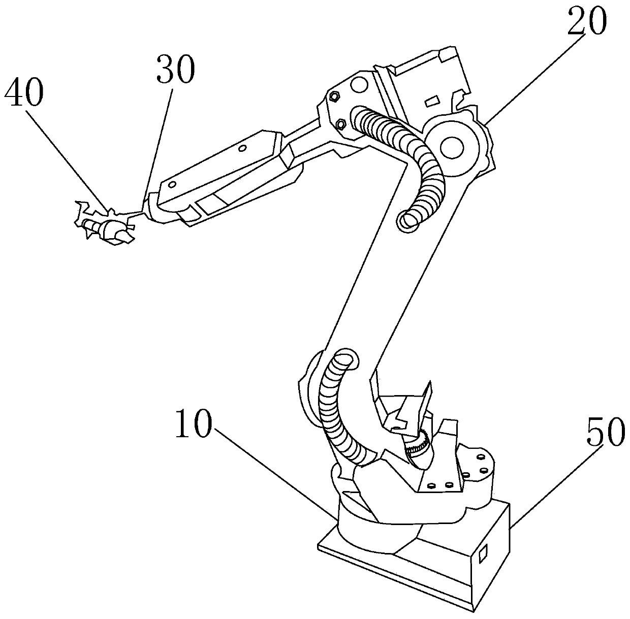
[0059] see figure 1 , is a schematic diagram of the appearance structure of a manipulator of a manipulator control system through vision positioning according to an embodiment of the present invention.

[0060] Among them: the first-level manipulator joint shaft control bearing 10; the second-level manipulator joint shaft control bearing 20; the third-level manipulator joint shaft control bearing 30; the industrial camera 40; the actuator 50.

[0061] The actuator is used to control the operation of the robotic arm.

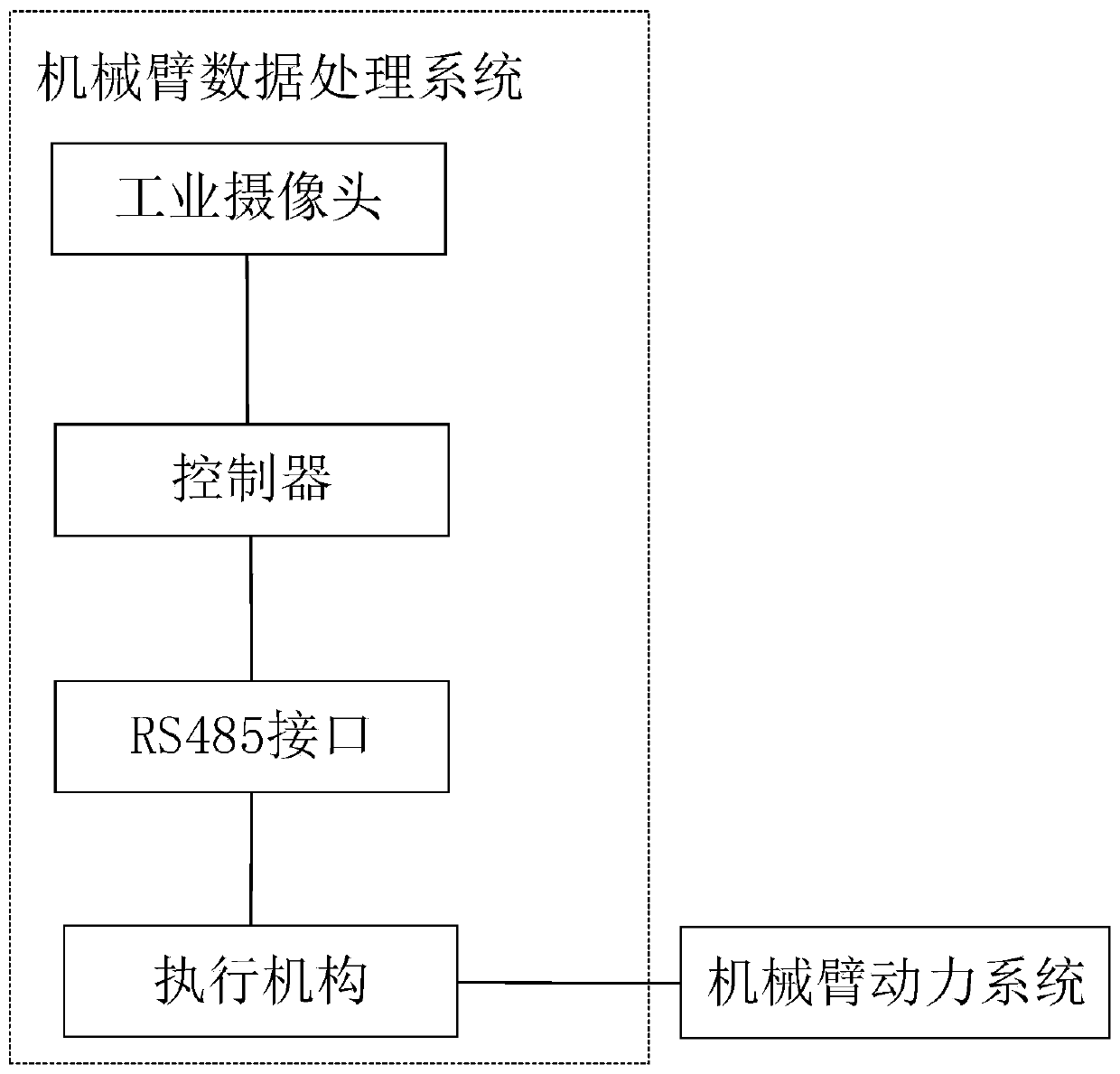
[0062] The industrial camera is used to collect pictures and video images, and send the data to the controller, and the controller analyzes the data collected by the industrial camera.

[0063] The schematic diagram of the appearance and structure of the robotic arm marks the specific position of the device. The position of the actuator can be changed to other positions, and the position of the industrial camera can also be adjusted according to the user's own n...

specific Embodiment approach

[0109] The mechanical arm is powered on, installed on the robot body, and reaches the work site through the movement of the robot body. The industrial camera collects image data through the binocular camera, and the image data is transferred to the actuator through the RS485 interface.

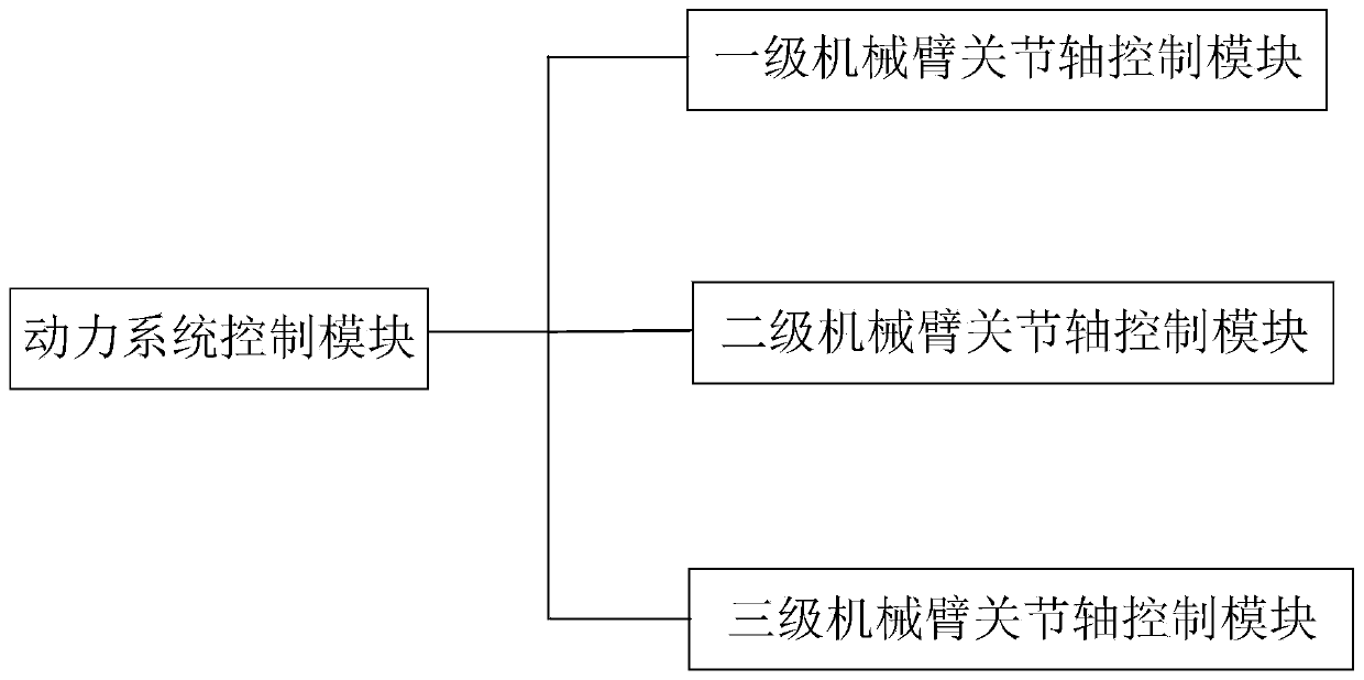
[0110] The actuator performs target detection and recognition according to the algorithm, and then sends the measured distance signal to the nearest joint axis of the manipulator, and sends it to the power system of each joint axis through different coordinate transformations to control the movement of the manipulator.

[0111] The specific process takes flame detection as an example:

[0112] The whole process is divided into target detection and depth ranging.

[0113] First train the deep learning model offline. Collect a large number of flame-related pictures, extract image features through convolutional neural network, and then use CNN, YOLO and other algorithms to train a flame recognit...


PUM


Abstract

A mechanical arm control system achieving positioning through vision comprises a mechanical arm data processing system and a mechanical arm power system. An industrial camera generates an image by capturing work environment video, and an executing mechanism recognizes data in the image for a processing module. According to the processing module, the distance measuring algorithm and the four-element algorithm are adopted for positioning a bearing of a target control mechanical arm, the mechanical arm is controlled to achieve the high-precision operation task, and control signals are generated to control the mechanical arm to move. Through the above manner, traditional mechanical arm single operation and poor work environment interaction are avoided, and the problem about difficult mechanical arm positioning is solved.

Description

technical field [0001] The invention relates to the field of intelligent manipulators, in particular to a manipulator control system through visual positioning. Background technique [0002] The robotic arm equipment currently used in the market is often with a fixed chassis. It handles a single task according to the setting of the program and cannot rotate 360°. Such robotic arm equipment often lacks precise positioning and object recognition functions during work. Working on a fixed target at a fixed position, the accuracy of the operation is not high, and the execution effect is poor. This shortcoming is even more fatal in some industries that require high precision. [0003] In addition to the poor interaction ability between the fixed chassis manipulator and the surrounding environment, the fire extinguishing equipment used in firefighting is operated by firefighters, and only fire extinguishing equipment has not been used in fire extinguishing scenarios. Such situation...

Claims


Application Information

Patent Timeline
Patent Type & Authority Applications(China)
IPC IPC(8): B25J9/16B25J5/00
CPCB25J5/007B25J9/1602B25J9/1697
Inventor 赵立恒
Owner 上海锵玫人工智能科技有限公司
Why Eureka
Try Eureka