Belt wheel type pipe conveying structure

A technology of feeding pipes and pulleys, applied in conveyors, conveyor objects, transportation and packaging, etc., can solve problems such as compression deformation, casing flattening, and labor intensity of workers.

Pending Publication Date: 2020-07-03
苏州创易技研股份有限公司
View PDF0 Cites 1 Cited by
  • Summary
  • Abstract
  • Description
  • Claims
  • Application Information

AI Technical Summary

Problems solved by technology

[0003] The technical problem to be solved by the present invention is to provide a pulley-type pipe delivery structure, which can adjust the distance between the pressure pipe transmission belt and the slotted transmission belt by adjusting the distance between the upper installation block and the lower installation block, so that it not only It can keep the shape of the casing from being squeezed and deformed, and still have enough friction to push the casing out smoothly. It also realizes the automatic feeding of the casing and is suitable for casings of various diameters and specifications. and the whole tube delivery process does not require manual operation. It has the advantages of high tube delivery efficiency, good tube delivery effect, smooth tube delivery process and the ability to ensure that the casing will not be squeezed and deformed. In addition, it not only effectively It solves the problems of low efficiency of pipe delivery, high labor intensity of workers and high labor cost of enterprises caused by the traditional method of manual pipe delivery. Tubes often suffer from flattening and deformation

Method used


Image

  • Belt wheel type pipe conveying structure
  • Belt wheel type pipe conveying structure
  • Belt wheel type pipe conveying structure

Examples


Embodiment Construction

[0017] In order to facilitate the understanding of the present invention, the present invention will be described more fully below with reference to the associated drawings. Preferred embodiments of the invention are shown in the accompanying drawings. However, the present invention can be embodied in many different forms and is not limited to the embodiments described herein. On the contrary, the purpose of providing these embodiments is to make the disclosure of the present invention more thorough and comprehensive.

[0018] Unless otherwise defined, all technical and scientific terms used herein have the same meaning as commonly understood by one of ordinary skill in the technical field of the invention. The terminology used herein in the description of the present invention is only for the purpose of describing specific embodiments, and is not intended to limit the present invention.

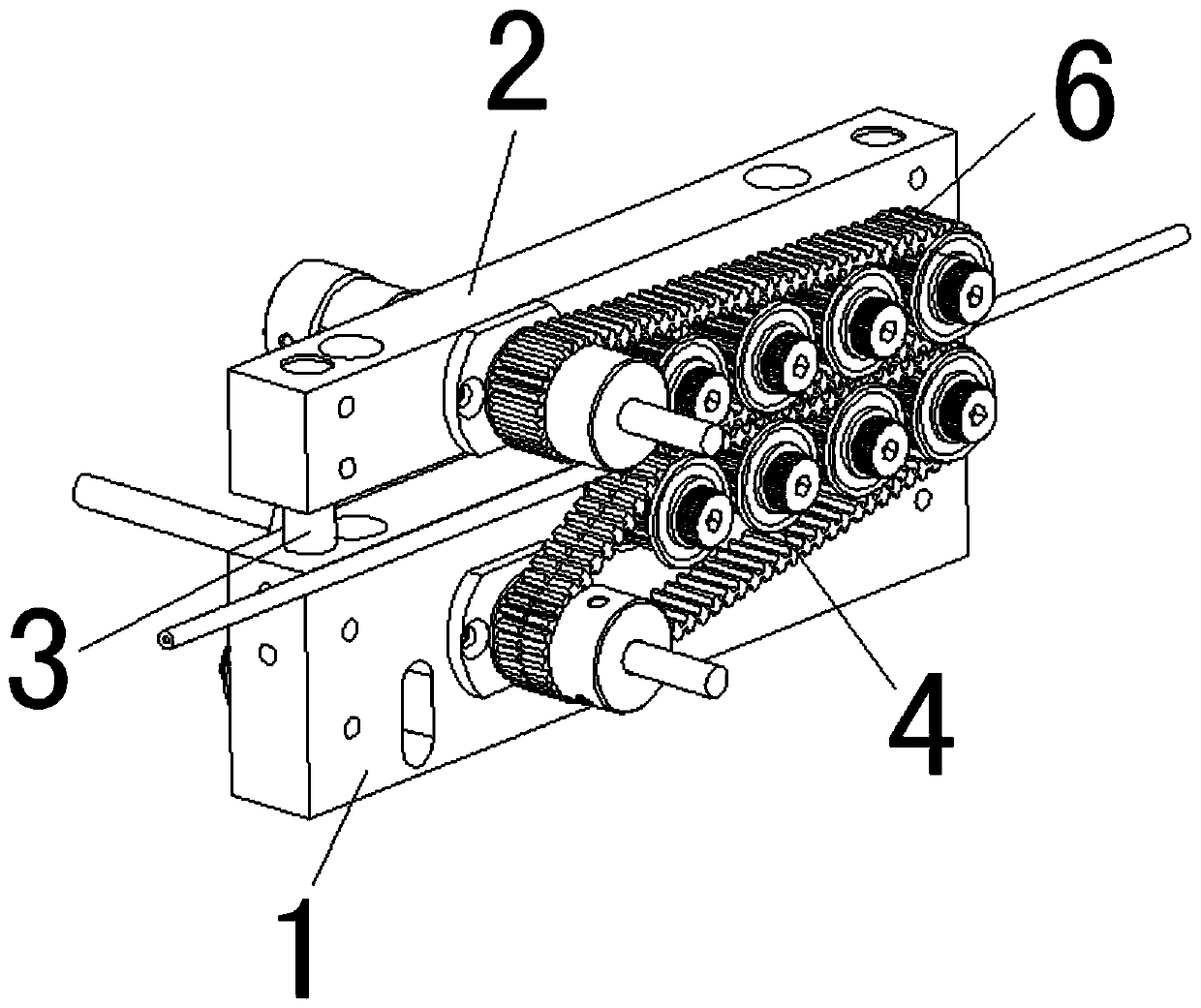
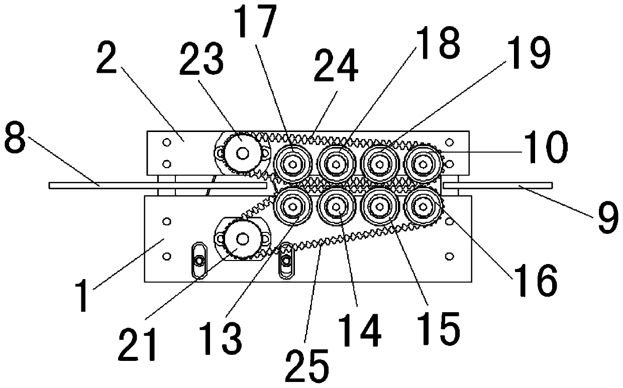
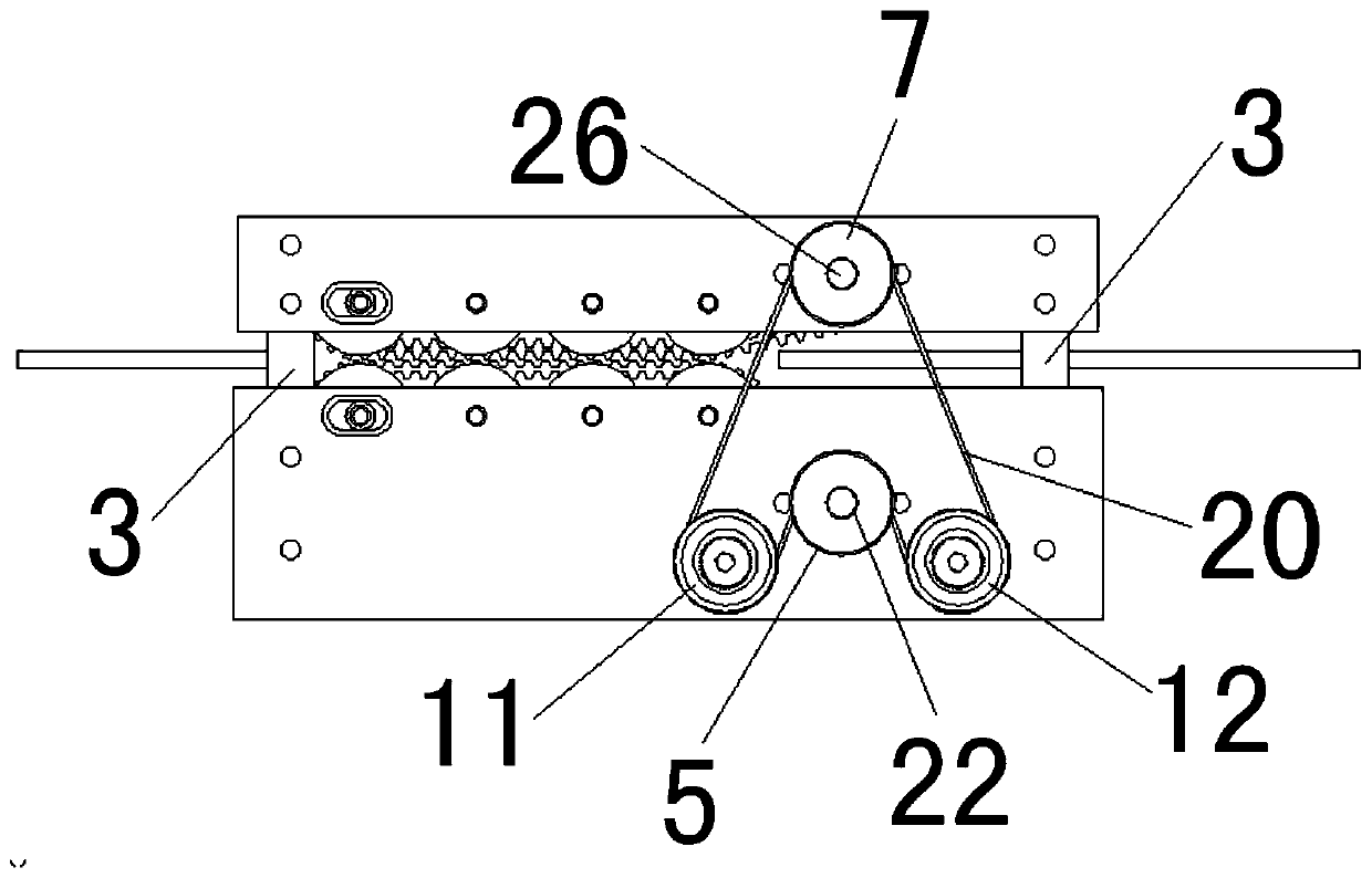
[0019] In this example, refer to Figure 1 to Figure 4 As shown, a pulley type pipe d...


PUM


Abstract

The invention discloses a belt wheel type pipe conveying structure. The belt wheel type pipe conveying structure comprises a lower installation block, an upper installation block, an installation column, a first transmission wheel assembly, a motor driving wheel, a second transmission wheel assembly, a pipe pressing driving wheel, a casing pipe input guide pin, a casing pipe output guide pin, a first transmission wheel, a second transmission wheel and transmission belts. By means of the overall structural design, enough frictional force still can be provided for smoothly conveying and pushingout casing pipes on the premise of keeping the shape of the casing pipes and preventing the casing pipes from extrusion deformation, and besides, the belt wheel type pipe conveying structure is suitable for conveying various casing pipes with different diameters and different specifications while achieving automatic pipe conveying; the whole pipe conveying process does not require workers to participate in operation, and the belt wheel type pipe conveying structure has the advantages that the pipe conveying efficiency is high, the pipe conveying effect is good, the pipe conveying process is smooth, and it can be ensured that the casing pipes are prevented from extrusion deformation; and moreover, the belt wheel type pipe conveying structure solves the problems of low pipe conveying efficiency and high labor intensity of workers of a traditional manual pipe conveying mode, and also solves the problem that the casing pipes are often flattened in a present pipe conveying mechanism.

Description

technical field [0001] The invention relates to a pulley type pipe feeding structure. Background technique [0002] The winding machine needs to put the wire through the casing before it can be wound. Traditionally, the wire is threaded through the casing by manual operation. The manual operation of the wire through the casing has low efficiency. , the effect of wearing the casing is poor, the labor intensity of the workers is high, and the labor cost of the enterprise is high. Later, some casing conveying mechanisms appeared on the market, but because their structural design was not yet perfect, they often caused the casing to be crushed, or the casing was not conveyed smoothly, and it was impossible to send casings of different specifications. The problem of the tube, it not only causes the qualified rate of the product to be low because the sleeve tube is crushed and deformed, but also seriously affects the efficiency of winding. Contents of the invention [0003] The...

Claims


Application Information

Patent Timeline
Patent Type & Authority Applications(China)
IPC IPC(8): B65G15/14B65G15/30B65G47/34B65G15/58
CPCB65G15/14B65G15/30B65G15/58B65G47/34B65G2201/0276
Inventor 刘世君杨波
Owner 苏州创易技研股份有限公司
Why Eureka
Try Eureka