
Knee joint prosthesis, hydraulic damper for artificial limb and energy storage acting method of hydraulic damper for artificial limb

A technology for hydraulic dampers and prostheses, which is applied in the fields of hydraulic dampers and knee joint prostheses. It can solve the problems of high quality, high cost, and bloated appearance of hydraulic dampers, and achieve low production costs, simple structure, stable and reliable structure. Effect

Pending Publication Date: 2020-07-03
浙江臻行科技有限公司
View PDF0 Cites 5 Cited by
  • Summary
  • Abstract
  • Description
  • Claims
  • Application Information

AI Technical Summary

Problems solved by technology

[0013] The main purpose of the present invention is to provide a knee joint prosthesis, a hydraulic damper for the prosthesis and its energy storage and work method, so as to solve the problem of bulky appearance, high quality and high cost of the hydraulic damper for the prosthesis in the prior art The problem

Method used


Image

  • Knee joint prosthesis, hydraulic damper for artificial limb and energy storage acting method of hydraulic damper for artificial limb
  • Knee joint prosthesis, hydraulic damper for artificial limb and energy storage acting method of hydraulic damper for artificial limb
  • Knee joint prosthesis, hydraulic damper for artificial limb and energy storage acting method of hydraulic damper for artificial limb

Examples


Embodiment Construction

[0031] It should be noted that the embodiments of the present invention and the features in the embodiments can be combined with each other if there is no conflict. Hereinafter, the present invention will be described in detail with reference to the drawings and in conjunction with the embodiments.

[0032] In order to enable those skilled in the art to better understand the solutions of the present invention, the technical solutions in the embodiments of the present invention will be described clearly and completely with reference to the accompanying drawings in the embodiments of the present invention. Obviously, the described embodiments are only It is a part of the embodiments of the present invention, not all the embodiments. Based on the embodiments of the present invention, all other embodiments obtained by those of ordinary skill in the art without creative work shall fall within the protection scope of the present invention.

[0033] It should be noted that the terms "fir...


PUM


Abstract

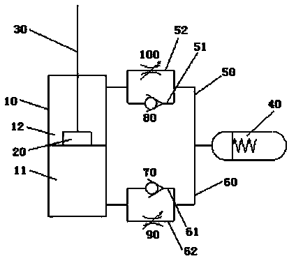
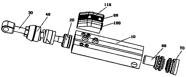
The invention provides a knee joint prosthesis, a hydraulic damper for an artificial limb and an energy storage acting method of the hydraulic damper for the artificial limb. The hydraulic damper forthe artificial limb comprises a hydraulic cylinder body, an energy storage device, a first one-way valve, a second one-way valve, a first control valve and a second control valve, wherein the energy storage device is installed on the hydraulic cylinder body, a first port of the energy storage device communicates with a rod chamber through a first pipeline, the first port of the energy storage device communicates with a rodless chamber through a second pipeline, the first pipeline comprises a first branch pipeline and a second branch pipeline which are arranged in parallel, and the second pipeline comprises a first branching pipeline and a second branching pipeline which are arranged in parallel; the first one-way valve is arranged on the first branching pipeline, and the second one-way valve is arranged on the first branch pipeline; and the first control valve is installed on the second branching pipeline, and the second control valve is installed on the second branch pipeline. The volume and mass of the whole damper can be reduced, the structure is simple, and thus the production cost of the hydraulic damper for the artificial limb is reduced.

Description

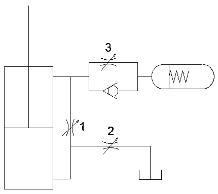
Technical field [0001] The present invention relates to the technical field of prosthetic components, in particular to a knee joint prosthesis, a hydraulic damper for the prosthesis and a method for accumulating energy. Background technique [0002] The hydraulic damper of the prosthesis is mainly composed of a single rod double-acting hydraulic cylinder, three throttle valves, a one-way valve, a spring accumulator and an oil tank. [0003] Such as figure 1 As shown, the working principle of the existing hydraulic damper with single rod double acting cylinder is as follows: [0004] a) In the first stage, the throttle valve 1 is opened, the throttle valve 2 and the throttle valve 3 are closed, and the piston rod moves downward under the action of external force. At this time, the single-rod double-acting hydraulic cylinder forms a differential connection. The hydraulic fluid passes through the throttle valve 1 from the rodless cavity, and part of it enters the rod cavity, and part o...

Claims


Application Information

Patent Timeline
IPC IPC(8): F15B1/02F15B11/08F15B13/04A61F2/64A61F2/74
CPCA61F2/64A61F2/68A61F2/74F15B1/02F15B11/08F15B13/04
Inventor 李哲金坤锋梁燕平冯琴琴申骏军谢浩玄利圣韩毓
Owner 浙江臻行科技有限公司
Learn More