
Electric direct-drive shaft torsional fatigue test device and method

A technology of torsional fatigue and test device, applied in the direction of measuring device, machine gear/transmission mechanism test, mechanical component test, etc., can solve the problems of poor versatility, high cost, oil leakage risk, etc. Good general effect

Active Publication Date: 2020-07-03
策仕(宁波)工业技术有限公司
View PDF11 Cites 5 Cited by
  • Summary
  • Abstract
  • Description
  • Claims
  • Application Information

AI Technical Summary

Problems solved by technology

[0003] The present invention overcomes the disadvantages of the existing hydraulic fatigue testing machine, such as high cost, poor versatility, and risk of oil leakage, and provides an electric direct-drive shaft torsion fatigue testing device and method, which has a simple structure, low cost, and universal Good performance, avoiding the risk of oil leakage

Method used


Image

  • Electric direct-drive shaft torsional fatigue test device and method
  • Electric direct-drive shaft torsional fatigue test device and method
  • Electric direct-drive shaft torsional fatigue test device and method

Examples


Embodiment 1

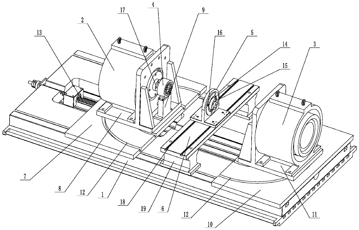
[0028] Embodiment 1: An electric direct drive shaft torsional fatigue test device (see attached figure 1 ), including installation platform 1, power direct drive main motor 2, power direct drive auxiliary motor 3, torque sensor 4, connecting seat 5 for clamping specimens, guide rail 6, movable slide plate 7 installed on the installation platform, power The direct drive main motor can be rotatably installed on the slide plate, the power direct drive auxiliary motor can be rotatably installed on the installation platform, and the connecting seat can be moved back and forth and installed on the guide rail between the power direct drive main motor and the power direct drive auxiliary motor. The torque sensor is placed between the power direct drive main motor and the power direct drive auxiliary motor, and the torque sensor is placed between the connecting seat and the power direct drive main motor. The power direct drive main motor and the power direct drive auxiliary motor are t...

Embodiment 2

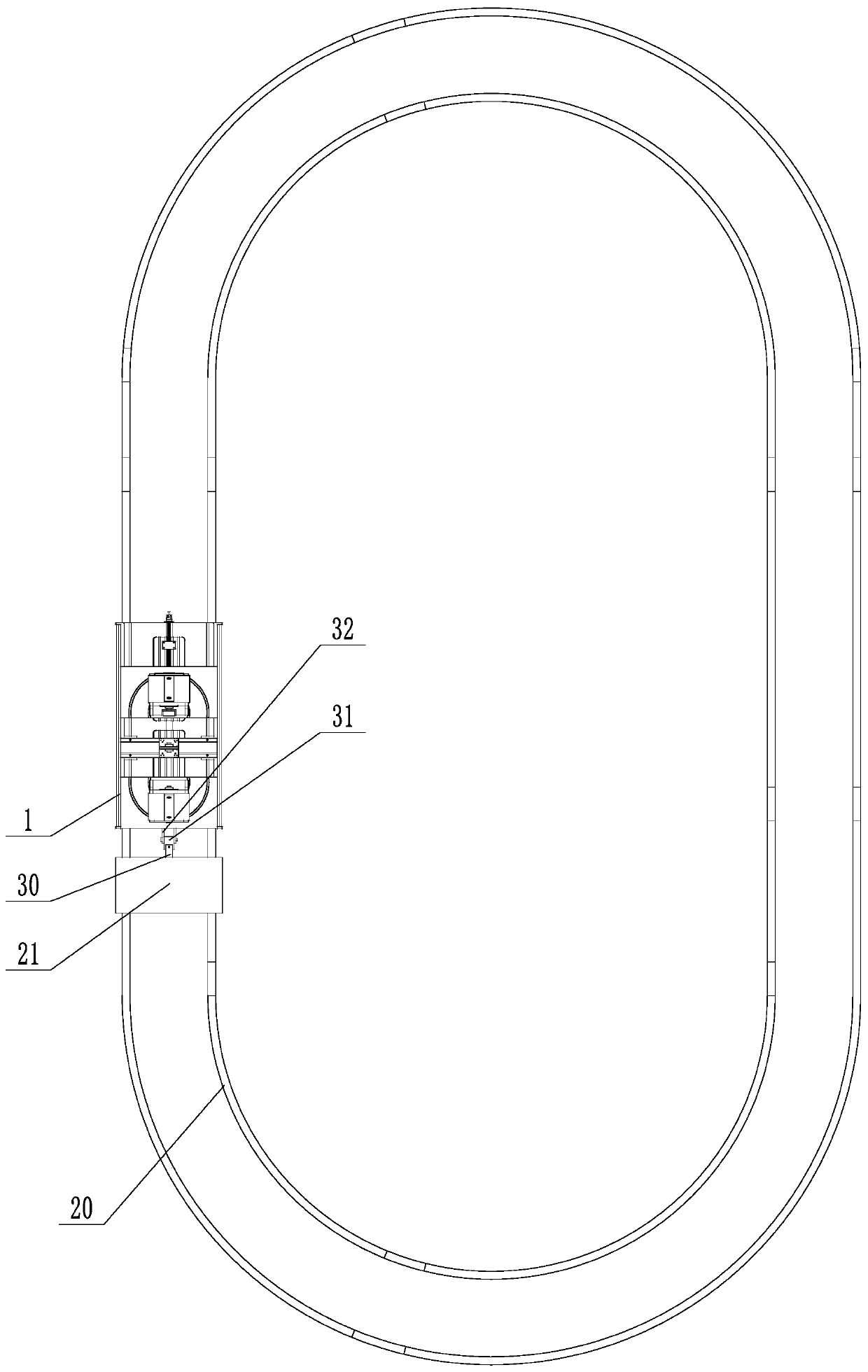
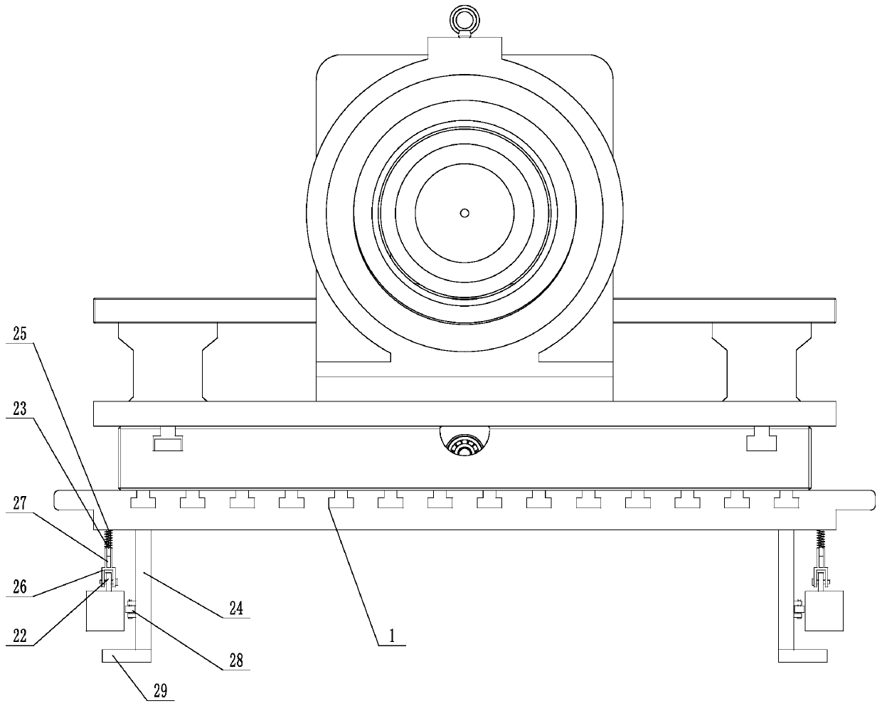
[0036] Embodiment 2: An electric direct drive shaft torsional fatigue test device (see attached figure 2 , attached image 3 ), its structure is similar to that of Example 1, the main difference is that the test device in this embodiment also includes a simulated driving track 20, a tractor 21 installed on the simulated driving track, the simulated driving track is waist-circular, and the lower surface of the installation platform The corner position is provided with wheels 22, and the wheels are supported on the upper surface of the simulated driving track. The tractor is connected with the installation platform and pulls the installation platform to simulate driving on the simulated driving track. The universal mechanism is connected between the tractor and the installation platform. The universal mechanism includes a connecting rod 30, a connecting block 31, and an extension support 32. The extension support is fastened to the front end of the installation platform, and th...


PUM


Abstract

The invention discloses an electric direct-drive shaft torsional fatigue test device and method, and aims to overcome defects of high cost, poor universality and oil leakage risk of an existing hydraulic fatigue test machine. The device comprises a mounting platform, a power direct-drive main motor, a power direct-drive auxiliary motor, a torque sensor and a connecting seat for clamping a test piece, wherein a movable sliding plate is mounted on the mounting platform, the power direct-drive main motor is rotatably mounted on the sliding plate, the power direct-drive auxiliary motor is rotatably mounted on the mounting platform, the connecting seat is movably mounted between the power direct-drive main motor and the power direct-drive auxiliary motor, the connecting seat is arranged betweenthe power direct-drive main motor and the power direct-drive auxiliary motor, and the torque sensor is arranged between the connecting seat and the power direct-drive main motor. The electric direct-drive shaft torsional fatigue test device is simple in structure, low in cost and good in universality, and the risk of oil leakage is avoided.

Description

technical field [0001] The invention relates to a fatigue test device, more specifically, it relates to an electric direct drive shaft torsion fatigue test device and method. Background technique [0002] Traditional torsional fatigue equipment mostly adopts hydraulic servo drive mode. This type of equipment needs to be equipped with auxiliary equipment such as hydraulic stations. The overall structure is relatively complicated and the efficiency is not high, and the energy consumption is relatively large. In addition, during the testing process of the hydraulic fatigue testing machine, the hydraulic oil is mixed with mechanical impurities and corrosive substances due to long-term use, resulting in the oil film strength of the hydraulic oil being insufficient to withstand the pressure of the working load, causing the metal surfaces to contact each other, resulting in friction. The force increases sharply, which accelerates the embarrassment of the parts, and the lubricating ...

Claims


Application Information

Patent Timeline
Patent Type & Authority Applications(China)
IPC IPC(8): G01M13/02G01M13/00
CPCG01M13/02G01M13/00
Inventor 俞岳平廖有用方涛沈明李境卢怡坤邹翼
Owner 策仕(宁波)工业技术有限公司
Learn More