
A medium-wave infrared continuous zoom lens and imaging device

A zoom lens, zoom lens technology, applied in optical components, instruments, optics, etc., can solve the problems of increasing the switching time of the field of view, focal plane drift, image quality degradation, etc., to achieve good imaging quality, short zoom stroke, smooth curve Effect

Active Publication Date: 2021-09-17
CHANGCHUN INST OF OPTICS FINE MECHANICS & PHYSICS CHINESE ACAD OF SCI
View PDF8 Cites 0 Cited by
  • Summary
  • Abstract
  • Description
  • Claims
  • Application Information

AI Technical Summary

Problems solved by technology

For the design of the 640×512-element staring focal plane array detector, the published literature includes: the patent of "A Mid-Wave Infrared Continuous Zoom Lens" by the Eleventh Research Institute of China Electronics Technology Group Corporation, which discloses a Applied to a 640×512 element 25μm cooled medium-wave detector, a focal length range of 50mm to 500mm, a zoom ratio of 10 times, and a medium-wave infrared continuous zoom lens with a maximum stroke of 123mm for the moving lens group, but the disadvantages of this patent are: The maximum stroke of the moving group is too long, which increases the switching time of the field of view and increases the difficulty of ensuring the coincidence accuracy of the wide and narrow field of view
However, because the system uses a three-component zoom method, the optical system has a complex structure and requires high control accuracy.
[0005] To sum up, the usual mid-wave infrared zoom lens is too long in axial dimension, and needs to bend the optical path through the screen mirror, and the space is large, so it is difficult to meet the actual use requirements of high zoom ratio and small size.
In addition, the optical materials used in infrared lenses are greatly affected by temperature, and their optical parameters such as refractive index, thickness, and radius of curvature will change with temperature, which will lead to focal plane drift and image quality degradation
When the lens moves to the telephoto end, the degradation of image quality caused by temperature is especially obvious
These above-mentioned problems have all greatly limited the applicability and application scope of present existing infrared zoom lens

Method used


Image

  • A medium-wave infrared continuous zoom lens and imaging device
  • A medium-wave infrared continuous zoom lens and imaging device
  • A medium-wave infrared continuous zoom lens and imaging device

Examples


Embodiment Construction

[0036] The following will clearly and completely describe the technical solutions in the embodiments of the present invention in conjunction with the accompanying drawings in the embodiments of the present invention. Obviously, the described embodiments are only some of the embodiments of the present invention, not all of them. Based on the embodiments of the present invention, all other embodiments obtained by persons of ordinary skill in the art without making creative efforts belong to the protection scope of the present invention.

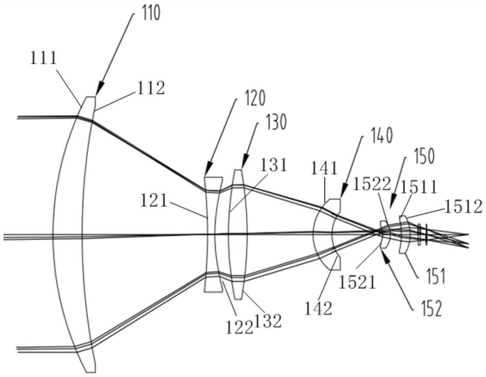
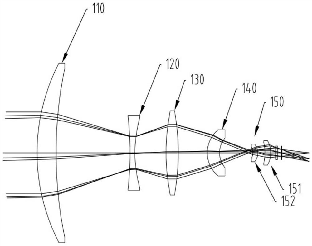
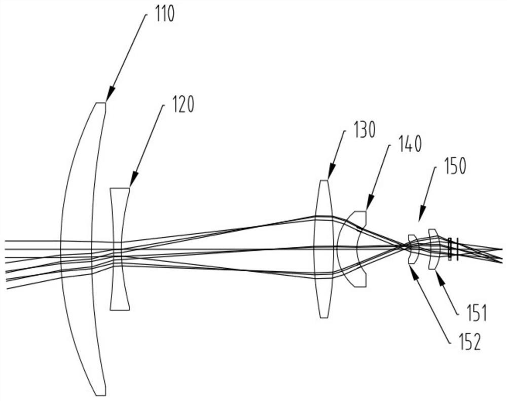
[0037] figure 1 It is a schematic diagram of the telephoto optical path of the mid-wave infrared continuous zoom lens according to the embodiment of the present invention. figure 2 It is a schematic diagram of the mid-focus optical path of the mid-wave infrared continuous zoom lens according to the embodiment of the present invention. image 3 It is a schematic diagram of the short-focus optical path of the mid-wave infrared continuous zoom len...


PUM


Abstract

The invention discloses a mid-wave infrared continuous zoom lens, in which a front fixed group, a zoom lens group, a compensation lens group, a rear fixed group and a secondary imaging lens group are arranged coaxially from the object side to the image side, and the front fixed group has positive refractive power, the zoom lens group has negative refractive power, the compensation lens group has positive refractive power, the rear fixed group has positive refractive power, the secondary imaging lens group has positive refractive power, the The zoom lens group and / or the compensation lens group can move axially to realize continuous zooming. The mid-wave infrared continuous zoom lens has a compact structure and meets the cold aperture efficiency of 100%; the axial movement of the zoom lens group and / or the compensation lens group realizes the continuous zoom of the system, the zoom stroke is short and the curve is smooth, and it can be used at full range Good image quality in the focal range.

Description

technical field [0001] The invention relates to the technical field of optical imaging, in particular to a mid-wave infrared continuous zoom lens and an imaging device. Background technique [0002] When the optical instrument is used in a large temperature range, the thermal expansion and contraction of the lens barrel material, the optical material, and the temperature refractive index coefficient of the optical material will change the focal power of the lens, resulting in defocusing phenomenon, while the heat of the lens barrel material Expansion and contraction will also cause the optical system to defocus and degrade the image quality. In order to reduce the impact of temperature changes on the imaging quality of the infrared optical system, an athermal design, or athermal difference design, is required, that is, through certain mechanical, optical and electronic technologies, to compensate the defocus caused by temperature changes, so that The infrared optical system...

Claims


Application Information

Patent Timeline
Patent Type & Authority Patents(China)
IPC IPC(8): G02B15/16G02B15/173G02B13/00
CPCG02B13/0045G02B13/008G02B13/009G02B15/16G02B15/173
Inventor 张新刘涛王灵杰史广维张建萍
Owner CHANGCHUN INST OF OPTICS FINE MECHANICS & PHYSICS CHINESE ACAD OF SCI
Learn More