
Image processing system

An image processing and image technology, applied in the field of image processing, can solve problems such as marker detection failure, and achieve the effect of avoiding detection failure and reducing workload

Active Publication Date: 2020-07-03
JILIN AGRI SCI & TECH COLLEGE
View PDF9 Cites 9 Cited by
  • Summary
  • Abstract
  • Description
  • Claims
  • Application Information

AI Technical Summary

Problems solved by technology

However, there are also some shortcomings. The marker recognition process is easily affected by factors such as marker reflection and occlusion, which may easily cause marker detection failure.

Method used


Image

  • Image processing system

Examples


Embodiment Construction

[0027] In order to make the objects and advantages of the present invention clearer, the present invention will be further described in detail below in conjunction with the examples. It should be understood that the specific embodiments described here are only used to explain the present invention, not to limit the present invention.

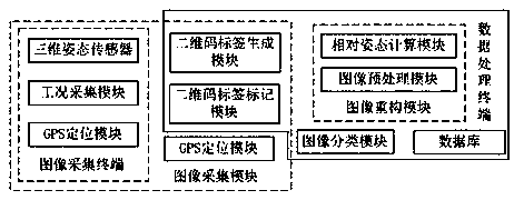
[0028] Such as figure 1 As shown, the embodiment of the present invention provides an image processing system, including:

[0029] The image acquisition module is used to acquire the target image of the built-in two-dimensional code label, the two-dimensional code label contains the lens model, the image acquisition mode, the three-dimensional posture information of the image acquisition terminal during image acquisition, and the position of the image acquisition terminal relative to the target acquisition / The distance and angle of the reference position;

[0030] The image reconstruction module is used to obtain the lens model corresponding...


PUM


Abstract

The invention discloses an image processing system. The system comprises: an image acquisition module, which is used for acquiring a target image internally loaded with a two-dimensional code label, an internally loaded lens model of the two-dimensional code label, an image acquisition mode, three-dimensional attitude information of an image acquisition terminal during image acquisition, and a distance and an angle of the image acquisition terminal relative to a target acquisition position / reference position; and an image reconstruction module is used for acquiring the lens model corresponding to the target image, the image acquisition mode, the three-dimensional attitude information of the image acquisition terminal during image acquisition, and the distance and angle of the image acquisition terminal relative to the target acquisition position / reference position, and completing the preprocessing of the image based on the requirements of the target image. According to the invention,a three-dimensional attitude sensor and a GPS positioning module are combined with the two-dimensional label technology to obtain the relative attitude information between the image acquisition terminal and the target acquisition position / reference position, and the situation of detection failure due to the influence of marker reflection or partial shielding factors is avoided.

Description

technical field [0001] The invention relates to the field of image processing, in particular to an image processing system. Background technique [0002] At present, the calculation of the relative attitude information of most cameras during image acquisition is based on markers, which are generally regular quadrilaterals, such as squares, surrounded by a black border on the outside of the marker, and coded inside to distinguish between different The purpose of marker detection is to locate the four corners of the marker, and its advantages are simple structure and easy identification. However, there are also some disadvantages. The marker recognition process is easily affected by factors such as marker reflection and occlusion, which may easily cause marker detection failure. Contents of the invention [0003] In order to solve the above problems, the present invention provides an image processing system, which avoids detection failures due to the reflection of marke...

Claims


Application Information

Patent Timeline
Patent Type & Authority Applications(China)
IPC IPC(8): G06K7/14G06K9/62G01S19/47G01C21/16G06N3/04
CPCG06K7/1417G06K7/1443G01S19/47G01C21/165G06N3/045G06F18/241
Inventor 孙明思
Owner JILIN AGRI SCI & TECH COLLEGE
Learn More