Pixel driving circuit and driving method thereof

A technology of a pixel driving circuit and a driving method, which is applied to instruments, static indicators, etc., can solve the problems of luminescence spectrum shift, high data transmission bandwidth requirements, and inability to support high resolution.

Active Publication Date: 2020-07-03
SHENZHEN CHINA STAR OPTOELECTRONICS SEMICON DISPLAY TECH CO LTD
View PDF19 Cites 21 Cited by
  • Summary
  • Abstract
  • Description
  • Claims
  • Application Information

AI Technical Summary

Problems solved by technology

Under different currents, the luminous spectrum of the LED will shift, which will lead to the problem of color shift
Although the existing conventional pulse width modulation (Pulse Width Modulation, PWM) driving technology can sol...

Method used


Image

  • Pixel driving circuit and driving method thereof
  • Pixel driving circuit and driving method thereof
  • Pixel driving circuit and driving method thereof

Examples


Embodiment Construction

[0021] The technical solutions in the embodiments of the present application will be clearly and completely described below in conjunction with the drawings in the embodiments of the present application. Apparently, the described embodiments are only some of the embodiments of this application, not all of them. Based on the embodiments in this application, all other embodiments obtained by those skilled in the art without making creative efforts belong to the scope of protection of this application.

[0022] In the description of the present application, it should be understood that the terms "center", "longitudinal", "transverse", "length", "width", "thickness", "upper", "lower", "front", " Orientation indicated by rear, left, right, vertical, horizontal, top, bottom, inside, outside, clockwise, counterclockwise, etc. The positional relationship is based on the orientation or positional relationship shown in the drawings, which is only for the convenience of describing the a...


PUM


Abstract

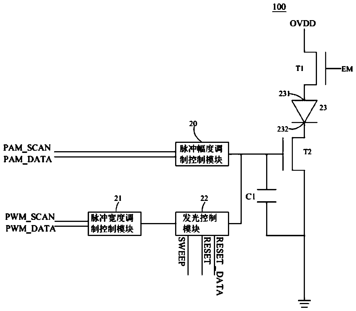
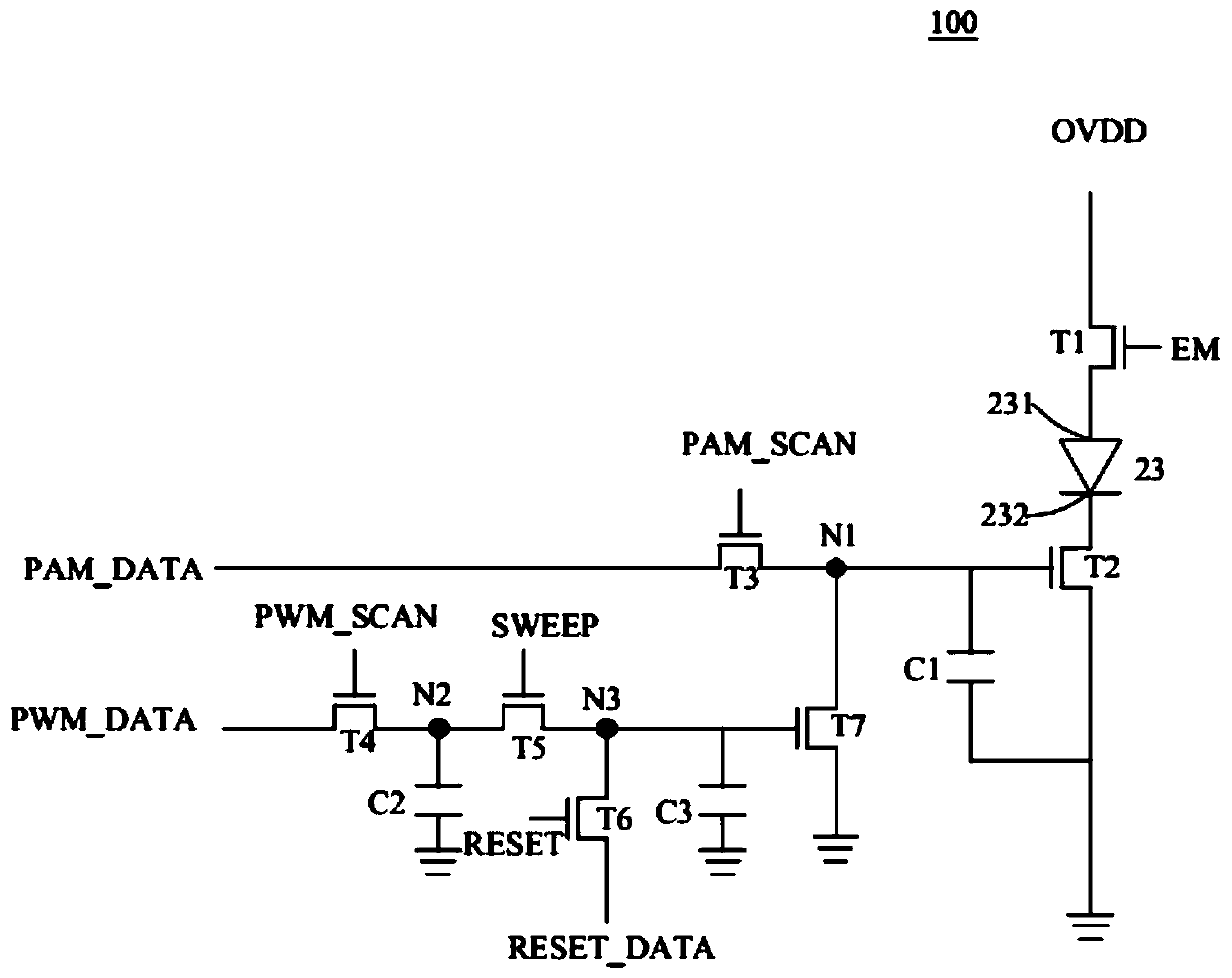
A pixel driving circuit comprises a light emitting diode, a second transistor, a pulse amplitude modulation transistor, a control transistor, a scanning transistor and a pulse width modulation transistor. The light emitting diode comprises an anode and a cathode. The input end of the second transistor is connected with the cathode. The output end of the pulse amplitude modulation transistor is connected with the control end of the second transistor. The input end of the control transistor is connected with the control end of the second transistor and the output end of the pulse amplitude modulation transistor. The output end of the scanning transistor is connected with the control end of the control transistor, the scanning transistor is configured to receive a control scanning signal, andthe time for controlling the scanning signal to reach the threshold voltage of the scanning transistor is the light-emitting time of the light-emitting diode. The output end of the pulse width modulation transistor is connected with the input end of the scanning transistor.

Description

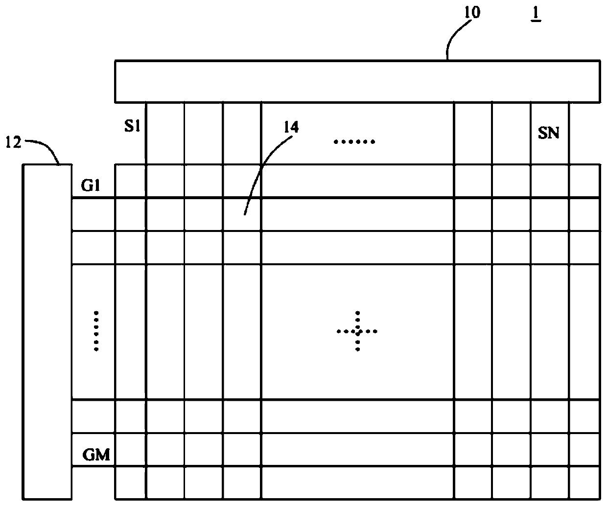
technical field [0001] The present application relates to the field of display technology, in particular to a pixel driving circuit and a driving method thereof. Background technique [0002] Light-emitting diodes (Light-Emitting Diode, LED), as high-efficiency, energy-saving, and environmentally friendly lighting fixtures, are increasingly replacing traditional lighting fixtures such as incandescent lamps. The energy saving of LED is reflected in the high luminous efficiency and adjustable light. Under different currents, the light emission spectrum of the LED will shift, which will lead to the problem of color shift. Although the existing conventional pulse width modulation (Pulse Width Modulation, PWM) driving technology can solve the problem of color shift, but because of the concept of sub-fields, the charging time is short and the data transmission bandwidth is high, so it cannot support high resolution. Drive technology has a limited range of applications. Content...

Claims


Application Information

Patent Timeline
IPC IPC(8): G09G3/32
CPCG09G3/32
Inventor 付建国黄泰钧王振岭
Owner SHENZHEN CHINA STAR OPTOELECTRONICS SEMICON DISPLAY TECH CO LTD
Why Eureka
Try Eureka