Miniaturized material irradiation device and use method thereof

An irradiation device and irradiation technology are applied in the field of miniaturized material irradiation devices, which can solve the problems of increasing the test cost, increasing the complexity of the irradiation device, and insufficient inflation, saving irradiation channel resources and improving comprehensive utilization efficiency. , the effect of reducing the exposure dose

Active Publication Date: 2020-07-03
NUCLEAR POWER INSTITUTE OF CHINA
View PDF10 Cites 1 Cited by
  • Summary
  • Abstract
  • Description
  • Claims
  • Application Information

AI Technical Summary

Problems solved by technology

[0006] This method has some disadvantages: firstly, it increases the complexity of the irradiation device, which makes manufacturing and assembling more difficult. This irradiation device is actually a kind of online irradiation, which needs to be added during the irradiation test. A

Method used


Image

  • Miniaturized material irradiation device and use method thereof
  • Miniaturized material irradiation device and use method thereof
  • Miniaturized material irradiation device and use method thereof

Examples


Embodiment 1

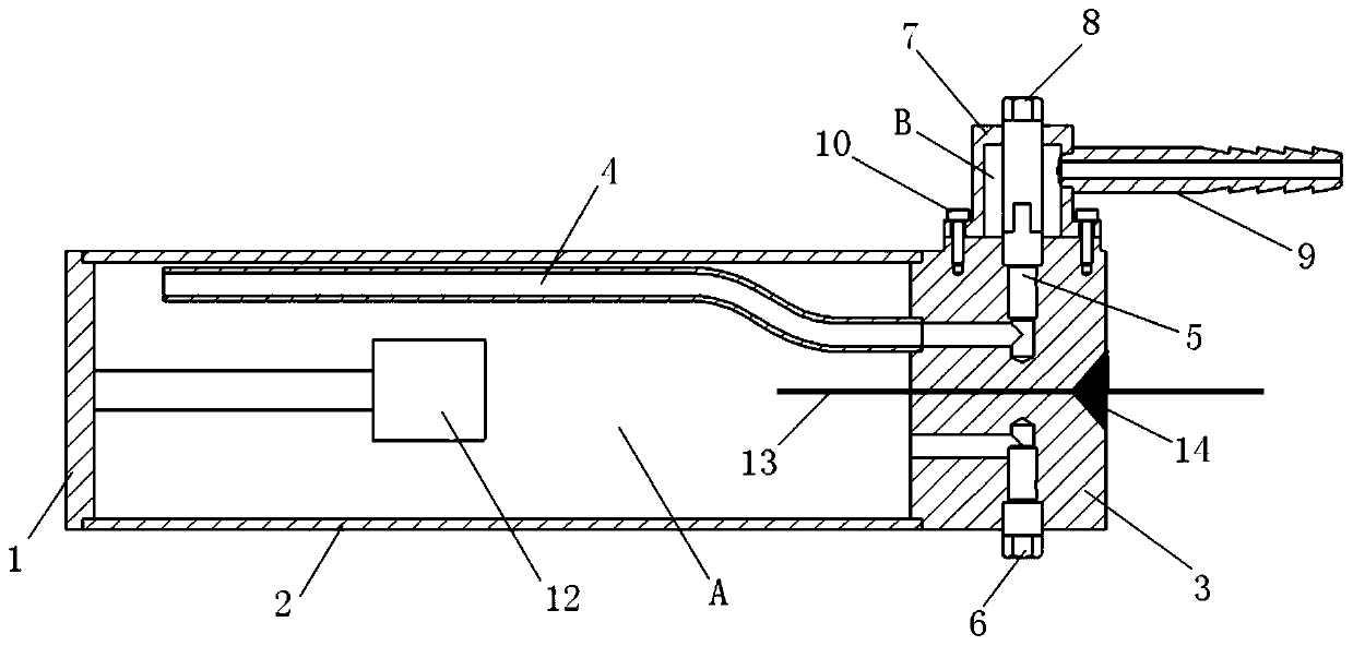
[0063] like figure 1 , figure 2 , image 3 , Figure 4 Shown:

[0064] A miniaturized material irradiation device, comprising an irradiation chamber A, one end of the irradiation chamber A is provided with an upper top cover 3, and the upper top cover 3 is provided with an air inlet hole and an air outlet hole;

[0065] Both the air inlet and the air outlet are located on the peripheral surface of the upper top cover 3, and an inflation screw 5 is arranged at the air inlet, and an exhaust screw 6 is arranged at the air outlet.

[0066] Design principle of the present invention is:

[0067] Since the structure of the traditional irradiation device is: including the irradiation chamber, the intake pipe and the exhaust pipe leading from the outside of the research reactor to the irradiation chamber inwardly, it is a semi-built-in structure, and its Part of the tube is built-in and part is outside, so that the radioactive rays can be directly transmitted to the top of the pi...

Embodiment 2

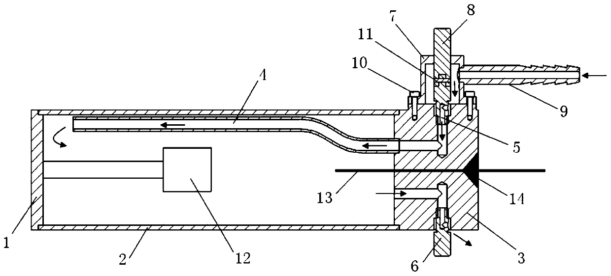
[0073] like figure 1 , figure 2 , image 3 , Figure 4 Shown:

[0074] On the basis of embodiment 1, further optimization technical scheme is:

[0075] The peripheral surface where the air inlet hole is located and the peripheral surface where the air outlet hole is located are two symmetrical peripheral surfaces. The air inlet and air outlet are arranged symmetrically, which can avoid the problems that the incoming gas is directly released to the air outlet, resulting in waste of gas and incomplete exhaust of the original gas.

Embodiment 3

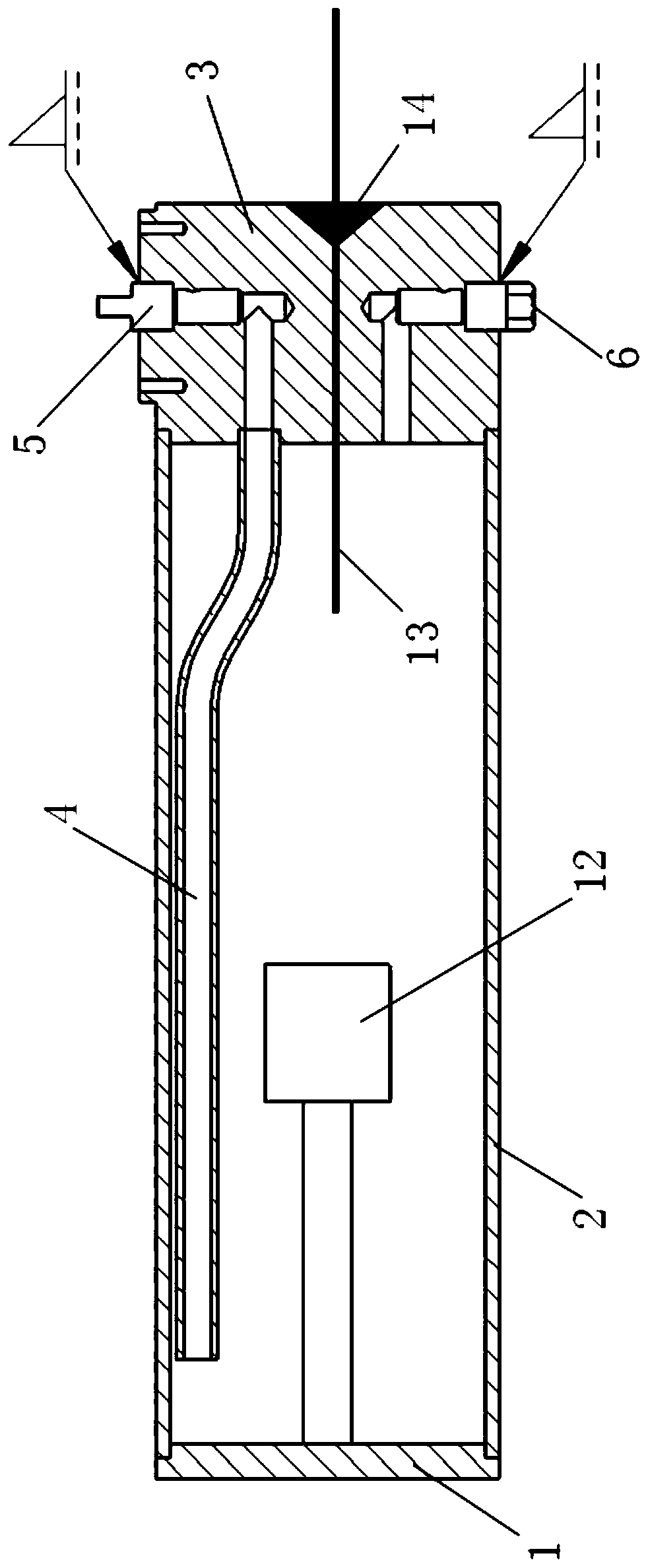
[0077] like figure 1 , figure 2 , image 3 , Figure 4 Shown:

[0078] On the basis of embodiment 1, further optimization technical scheme is:

[0079] The axis of the air inlet hole or / and the air outlet hole is perpendicular or oblique to the corresponding peripheral surface.

[0080] specific, figure 1 As shown, when the vertical setting is adopted, corresponding communication channels need to be configured to communicate with the irradiation chamber A; not shown in the figure, when obliquely intersecting, the air inlet or / and air outlet can be directly obliquely connected to the irradiation chamber The room A is connected, or it can be connected with the irradiation chamber A through a connecting channel after being obliquely crossed.


PUM


Abstract

The invention discloses a miniaturized material irradiation device which comprises an irradiation chamber A. One end of the irradiation chamber A is provided with an upper top cover, the upper top cover is provided with an air inlet hole and an air outlet hole, the air inlet hole and the air outlet hole are both located in the circumferential direction of the upper top cover, an inflation screw plug is arranged at the air inlet hole, and an exhaust screw plug is arranged at the air outlet hole. According to the device, an air inlet pipe and an air outlet pipe which are communicated with the irradiation chamber and the outside of the research reactor are avoided, and the upper top cover is additionally arranged on one side of the irradiation chamber A, the air inlet hole and the air outlethole are formed in the upper top cover, the control plug is adopted to seal the air inlet hole and the air outlet hole, and the screw plug is utilized to seal the upper top cover after the upper top cover is pre-filled with air, so that the longitudinal length of the irradiation device is reduced, and the miniaturization design is realized.

Description

technical field [0001] The invention relates to the field of nuclear engineering irradiation devices, specifically a miniaturized material irradiation device and a method of use, and its technical branches should be classified under the IPC classification of G21K5 / 00. Background technique [0002] The role of the irradiation device is to: [0003] In order to know the effect of reactor neutron irradiation on the material performance, it is necessary to test the material. The irradiation test is carried out in the irradiation tunnel of the research reactor, and a special irradiation test device (irradiation device or irradiation target) must be designed and processed. [0004] Common problems with irradiators include: [0005] In order to achieve heat insulation or other test conditions during the radiation test, it is necessary to fill the radiation device with heat insulation and protective gas. The existing method is often as follows: the irradiation device includes the...

Claims


Application Information

Patent Timeline
IPC IPC(8): G21K5/00
CPCG21K5/00
Inventor 吴红伟斯俊平聂良兵杨文华童明炎孙胜徐斌江丽娟张帅张亮赵文斌
Owner NUCLEAR POWER INSTITUTE OF CHINA
Why Eureka
Try Eureka