Novel SE Mark point graph structure and preparation method thereof

A new type of dot pattern technology, applied in the field of SEMark dot pattern structure and its preparation, can solve the problems of low production time, high stability, Mark point damage cost, etc., and achieve shortened production time, good stability, and good alignment of points. The effect of topography

Inactive Publication Date: 2020-07-03
HENGDIAN GRP DMEGC MAGNETICS CO LTD
View PDF4 Cites 4 Cited by
  • Summary
  • Abstract
  • Description
  • Claims
  • Application Information

AI Technical Summary

Problems solved by technology

[0004] The present invention aims to overcome the problem that the graphics in the prior art are prone to secondary processing in the same area, resulting in Mark point damage, high cost, low stability, and long production time, and provides a novel SE Mark point graphic structure and its preparation method. The present invention The unique Mark point graphics can avoid the problem of secondary processing of the same area encountered by conventional Mark graphics, and reduce the damage at the Mark point. The graphics are fully compatible with existing laser doping equipment, which greatly reduces costs and facilitates industrial production Good medium stability, production time ≤ 0.1s, which greatly shortens the entire laser marking time and improves production capacity
The cross-shaped mark point pattern avoids the problem of secondary processing in the same area encountered by the conventional concentric circle mark point pattern, which reduces the damage of the mark point. The cross mark point pattern is compatible with the existing laser doping equipment and shortens the The time of laser marking greatly improves the production capacity, and the cross mark pattern is better and easier to be recognized by the equipment camera during the printing process, reducing the number of alarms and the processing technology is simple

Method used


Image

  • Novel SE Mark point graph structure and preparation method thereof
  • Novel SE Mark point graph structure and preparation method thereof

Examples


Embodiment

[0049] A kind of novel SE Mark dot graphic structure of the present embodiment, such as figure 1 As shown, including the silicon wafer and four Mark points, the four Mark points are all cross-shaped structures, and the Mark points include two mutually perpendicular straight lines, one of which has a gap, and the gap passes through the other line, and the Mark point is lasered The four corners of the silicon wafer are used for PERC stacked selective emitter technology.

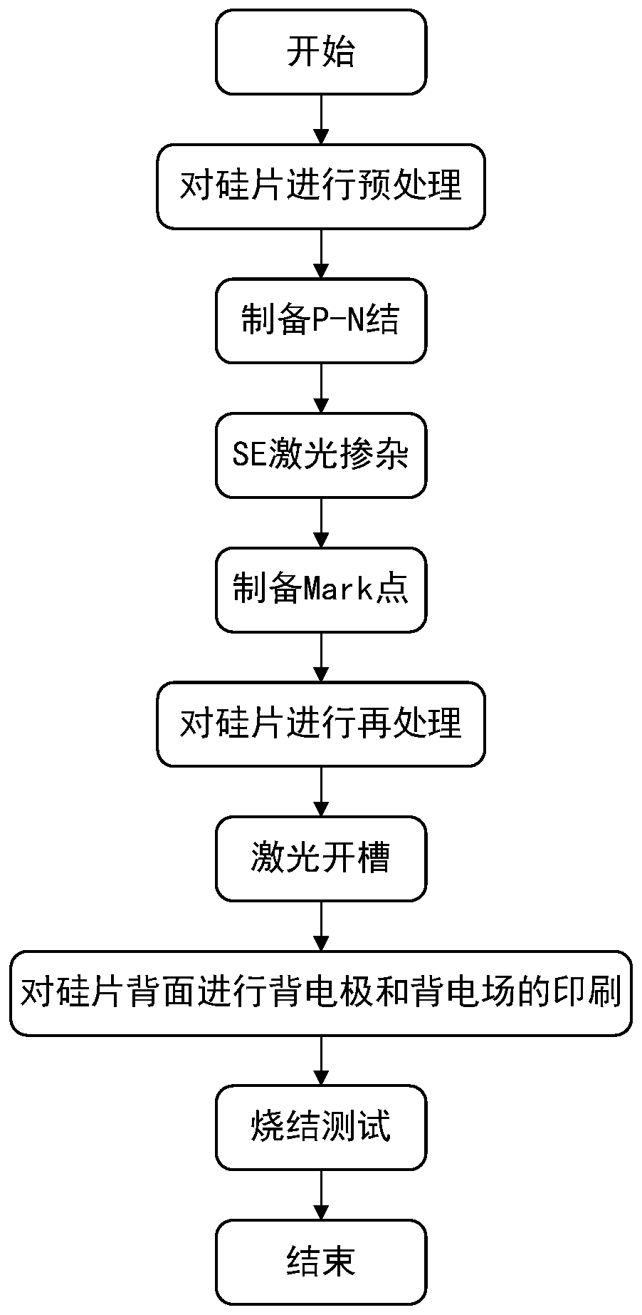
[0050] The present invention also provides a kind of preparation method of novel SE Mark dot pattern structure correspondingly, such as figure 2 As shown, it specifically includes the following steps:

[0051] S1: Pretreating the silicon wafer;

[0052] Wherein, step S1 specifically includes the following steps:

[0053] S11: pre-cleaning the silicon wafer;

[0054] S12: Prepare the textured surface of the silicon wafer.

[0055] S2: preparing a P-N junction;

[0056] Wherein, step S2 specifically includ...


PUM


Abstract

The invention discloses a novel SE Mark point graph structure and a preparation method thereof. A purpose of the invention is to solve the problems of Mark point damage, high cost, low stability and long manufacturing time caused by secondary processing of the same area in a graph in the prior art. The novel SE Mark point graph structure comprises a silicon wafer body and a plurality of Mark points, wherein the Mark points are of a cross-shaped structure, and the Mark points are subjected to laser in the four corner areas of the silicon wafer body and used for a PERC superposition selective emitter technology. According to the invention, through the special Mark points, the production efficiency can be improved and the productivity can be improved in the production process, the number of device alarms is reduced, and the production time is greatly shortened; the preparation method is convenient for equipment identification, is good in stability in the industrial production process, andis completely compatible in equipment; and four cross-shaped Mark points are obtained through laser so as to achieve good alignment point morphology and convenient recognition, transverse lines and vertical lines cannot be overlapped for marking in the marking process, an equipment camera can conduct recognition more easily in the printing process, the number of times of alarming is reduced, andthe industrial production efficiency is effectively improved.

Description

technical field [0001] The present invention relates to the technical field of laser marking, in particular to a new type of laser marking technology that prevents overlapping and reaching standards during the marking process, prevents damage to Mark points, better and easier identification of equipment cameras during printing, reduces the number of alarms, and has simple processing technology, reduces processing time and improves production capacity. SE Mark dot pattern structure and its preparation method. Background technique [0002] Solar energy is an inexhaustible renewable energy source for human beings. It is also a clean energy source and does not produce any environmental pollution. Among the effective utilization of solar energy; solar photovoltaic utilization is the fastest growing and most dynamic research field in recent years, and it is one of the most watched projects. To this end, people have researched and developed solar cells. The production of solar ce...

Claims


Application Information

Patent Timeline
Patent Type & Authority Applications(China)
IPC IPC(8): H01L23/544H01L31/18
CPCH01L23/544H01L31/1804Y02P70/50
Inventor 王建
Owner HENGDIAN GRP DMEGC MAGNETICS CO LTD
Why Eureka
Try Eureka