Waveguide port cavity dielectric filter

A dielectric filter and waveguide port technology, applied in the field of filters, can solve the problems of out-of-band suppression and temperature drift limitation, high quality factor, unobtainable, etc., and achieve excellent performance indicators, good electrical performance, and facilitate mass production.

Pending Publication Date: 2020-07-03
NANJING HMC SYST CO LTD +1
View PDF0 Cites 0 Cited by
  • Summary
  • Abstract
  • Description
  • Claims
  • Application Information

AI Technical Summary

Problems solved by technology

Due to its own loss, the traditional metal cavity filter cannot obtain a high quality factor when the cavity size is limited, resulting in certain restrictions on indicators such as out-of-band rejection and temperature drift.

Method used


Image

  • Waveguide port cavity dielectric filter
  • Waveguide port cavity dielectric filter
  • Waveguide port cavity dielectric filter

Examples


Embodiment 1

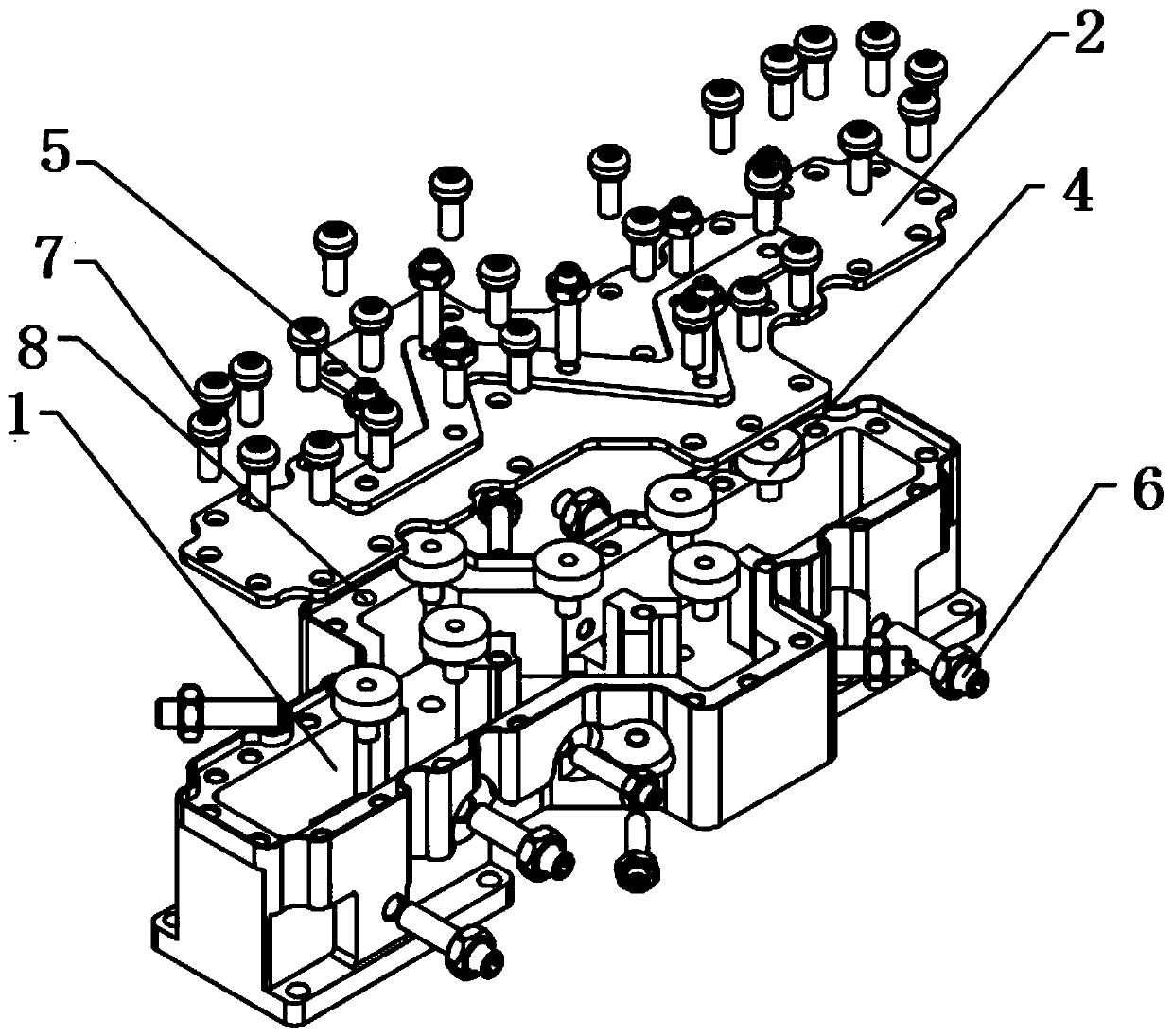
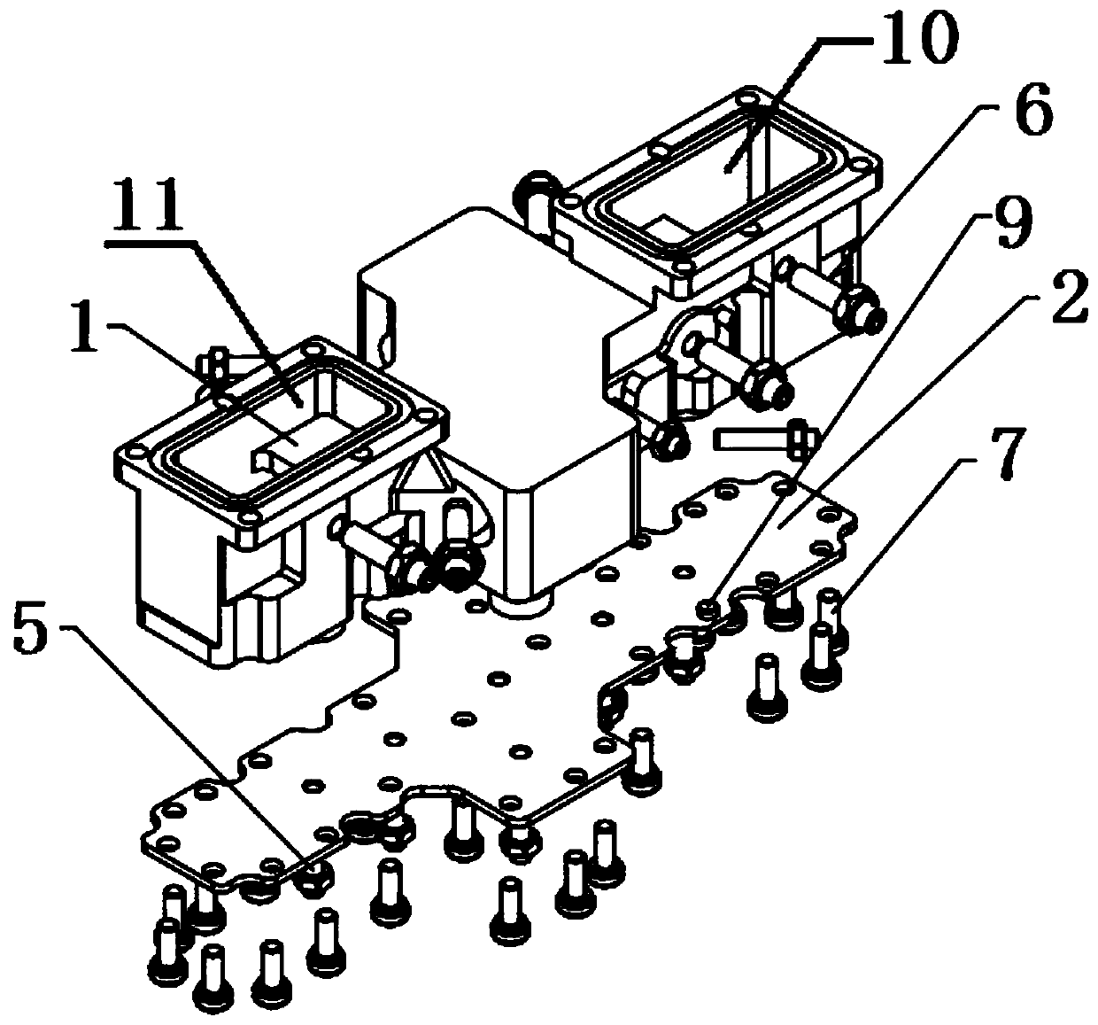
[0033] A waveguide cavity dielectric filter, including a cavity 1, a cover plate 2, several dielectric resonators 4, several frequency tuning screws 5 and several coupling tuning screws 6, there are at least two dielectric resonators 4,

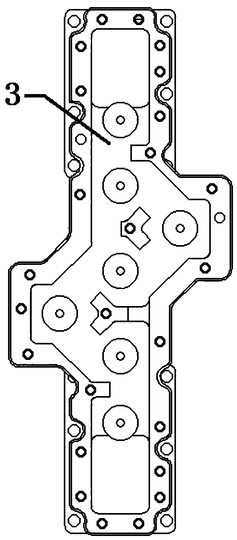
[0034] The upper surface of the cavity 1 is provided with a receiving groove, several dielectric resonators 4 are fixedly arranged at the bottom of the receiving groove, the cover plate 2 is fixedly arranged on the cavity body 1, and the lower ends of several frequency tuning screws 5 pass through the cover plate 2 and extend into the receiving groove , a number of frequency tuning screws 5 are rotationally connected or slidingly connected to the cover plate 2, there is a frequency tuning screw 5 above the dielectric resonator 4, and a number of coupling tuning screws 6 extend transversely through the side wall of the cavity 1 into the accommodation groove, Several coupling tuning screws 6 are rotationally connected or slidingly connected to t...

Embodiment 2

[0053] A waveguide cavity dielectric filter, including a cavity 1, a cover plate 2, several dielectric resonators 4, several frequency tuning screws 5 and several coupling tuning screws 6, there are at least two dielectric resonators 4,

[0054] The upper surface of the cavity 1 is provided with a receiving groove, several dielectric resonators 4 are fixedly arranged at the bottom of the receiving groove, the cover plate 2 is fixedly arranged on the cavity body 1, and the lower ends of several frequency tuning screws 5 pass through the cover plate 2 and extend into the receiving groove , a number of frequency tuning screws 5 are rotationally connected or slidingly connected to the cover plate 2, there is a frequency tuning screw 5 above the dielectric resonator 4, and a number of coupling tuning screws 6 extend transversely through the side wall of the cavity 1 into the accommodation groove, Several coupling tuning screws 6 are rotationally connected or slidingly connected to t...


PUM


Abstract

The invention discloses a waveguide port cavity dielectric filter. An accommodating groove is formed in the upper surface of the cavity. The dielectric resonator is fixedly arranged at the bottom of the accommodating groove. The cover plate is fixedly arranged on the cavity. The lower end of the frequency tuning screw penetrates through the cover plate and extends into the accommodating groove. The frequency tuning screws are rotatably or slidably connected with the cover plate, one frequency tuning screw is arranged above each dielectric resonator, the coupling tuning screws transversely penetrate through the side wall of the cavity and extend into the accommodating groove, the coupling tuning screws are rotatably or slidably connected with the side wall of the cavity, and at least one coupling tuning screw is arranged between every two dielectric resonators. A signal input waveguide port is formed in the left end of the cavity bottom wall, a signal output waveguide port is formed inthe right end of the cavity bottom wall, and the signal input waveguide port and the signal output waveguide port communicate with the containing groove. The dielectric filter has the advantages of low insertion loss and wide waveguide working frequency range, and better electrical performance and smaller filter volume under the same frequency are obtained by replacing the cavity waveguide resonator with the dielectric resonator.

Description

technical field [0001] The invention relates to a waveguide cavity body dielectric filter, which belongs to the technical field of filters. Background technique [0002] In modern communication systems, microwave radio frequency devices are an important part. A filter is a basic radio frequency unit, and a series of indicators such as insertion loss, out-of-band rejection, power capacity, and volume have an important impact on the performance of the entire communication system. Due to its own loss, the traditional metal cavity filter cannot obtain a high quality factor when the cavity size is limited, resulting in certain restrictions on indicators such as out-of-band rejection and temperature drift. In traditional filter design, the coupling between two resonators is generally controlled by the distance between the resonators or the size of the coupling window between the two resonators. Coupling tuning screws are only used to fine-tune coupling to offset machining errors...

Claims


Application Information

Patent Timeline
Patent Type & Authority Applications(China)
IPC IPC(8): H01P1/20H01P7/10
CPCH01P1/2002H01P7/10
Inventor 陆聆曾志华刘银银刘晨曦
Owner NANJING HMC SYST CO LTD
Why Eureka
Try Eureka