Power conversion circuit for LCC-S wireless power transmission system

A technology of wireless power transmission, LCC-S, applied in high-efficiency power electronic conversion, output power conversion device, DC power input conversion to DC power output, etc., can solve the disadvantages of wireless power transmission technology promotion, large number of devices, loss Large and other problems, to achieve the effect of reducing switching loss and reverse recovery loss, reducing the number of components, and reducing conduction loss

Inactive Publication Date: 2020-07-03
JIANGSU FRONTIER ELECTRIC TECH +2
View PDF18 Cites 1 Cited by
  • Summary
  • Abstract
  • Description
  • Claims
  • Application Information

AI Technical Summary

Problems solved by technology

In a traditional wireless power transmission system, a diode uncontrolled rectifier and a DC chopper circuit are usually used to form a power conversion circuit at the receiving end. The circuit is simple to control, but the number of components is large, and the loss in high-frequency and high-power occasions such as wireless charging of electric vehicles is relatively large. Large, not conducive to the promotion of wireless power transmission technology

Method used


Image

  • Power conversion circuit for LCC-S wireless power transmission system
  • Power conversion circuit for LCC-S wireless power transmission system
  • Power conversion circuit for LCC-S wireless power transmission system

Examples


Embodiment Construction

[0017] Embodiments of the present invention will be described in further detail below in conjunction with the accompanying drawings.

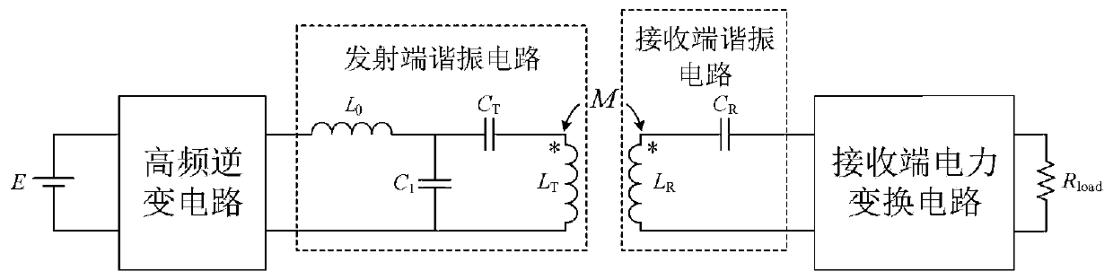
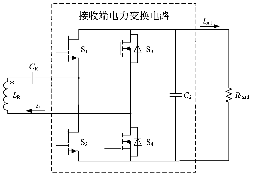
[0018] Such as figure 1 As shown, the present invention is a power conversion circuit for an LCC-S wireless power transmission system, which includes a high-frequency inverter circuit, a transmitting-end resonant circuit, a receiving-end resonant circuit, and a receiving-end power change circuit connected in sequence; The high-frequency inverter circuit is connected to a DC power supply, the receiving-end resonant circuit is connected to a load, and the receiving-end power changing circuit includes a switching tube S1, a switching tube S2, a switching tube S3, a switching tube S4, and a filter capacitor C2; When the current generated by the resonant circuit at the receiving end is positive, the switch tube S1, switch tube S2, switch tube S4 and filter capacitor C2 form a boost circuit; when the current generated by the resonant circuit at the r...


PUM


Abstract

The invention discloses a power conversion circuit for an LCC-S wireless power transmission system. The power conversion circuit comprises a high-frequency inverter circuit, a transmitting end resonance circuit, a receiving end resonance circuit and a receiving end power change circuit, the high-frequency inverter circuit is connected with a direct-current power supply, the receiving end resonancecircuit is connected with a load, and the receiving end power change circuit comprises a switching tube S1, a switching tube S2, a switching tube S3, a switching tube S4 and a filter capacitor C2; when the current generated by the receiving end resonance circuit is positive, the switching tube S1, the switching tube S2, the switching tube S4 and the filter capacitor C2 form a boosted circuit; andwhen the current generated by the receiving end resonance circuit is negative, the switching tube S1, the switching tube S2, the switching tube S3 and the filter capacitor C2 form a boosted circuit.According to the circuit, the topological structure of a receiving end power conversion circuit is changed, and the number of devices is reduced; a GaN FET is selected as a high-frequency switching device, so that the switching loss and reverse recovery loss of the high-frequency device are greatly reduced; and a synchronous rectification technology is adopted, so that the conduction loss of the device is further reduced.

Description

technical field [0001] The invention belongs to the technical field of wireless power transmission, and in particular relates to a power conversion circuit used in an LCC-S wireless power transmission system. Background technique [0002] Wireless power transmission is a technology that does not require electrical connections for power transmission. It can overcome the problems faced by traditional wired power transmission technologies in use, such as avoiding insulation aging and poor contact that may be caused by exposed connecting wires, and improving the safety of power transmission. sex. In the field of electric vehicles, it has a good application prospect, which can make the charging of electric vehicles more flexible and convenient, especially the dynamic wireless power transmission technology, which helps to solve problems such as mileage anxiety. [0003] The LCC-S resonant compensation topology is a kind of magnetically coupled resonant wireless power transmission...

Claims


Application Information

Patent Timeline
Patent Type & Authority Applications(China)
IPC IPC(8): H02J50/12H02J50/70H02M3/335
CPCH02M3/33592H02J50/12H02J50/70H02M1/0054Y02B70/10
Inventor 潘志新杨晓梅王成亮徐妍费益军彭涛胡鹏刘玙谭林林李昊泽黄学良
Owner JIANGSU FRONTIER ELECTRIC TECH
Why Eureka
Try Eureka