Check patentability & draft patents in minutes with Patsnap Eureka AI!

High-precision low-jitter clock recovery system

A clock recovery, low jitter technology, applied in the direction of automatic power control, electrical components, etc., can solve the problems of receiver clock lockout, high-speed code stream inter-symbol interference, communication system interruption, etc., to improve phase detection accuracy, debugging Low difficulty and good consistency

Active Publication Date: 2020-07-03
NO 54 INST OF CHINA ELECTRONICS SCI & TECH GRP
View PDF2 Cites 0 Cited by
  • Summary
  • Abstract
  • Description
  • Claims
  • Application Information

AI Technical Summary

Problems solved by technology

In the scattering fading channel, when the information is transmitted over a short distance, the clock can be extracted through the envelope. However, due to the time-varying and multipath effects of the scattering channel itself, the signal envelope will be distorted. If the existing clock recovery algorithm is used , when the rate is 64kb / s, only when the clock drift reaches 15.625 microseconds, the clock will be re-locked and calibrated. If there are multi-hop relays in the link, each hop will introduce the relay chain Link clock drift and jitter. After more than two hops in the wireless channel, the link clock jitter will accumulate and increase. In severe cases, the clock of the farthest receiver will lose lock, causing the communication system to be interrupted.
In recent years, the information transmission rate has been getting higher and higher, and the high-speed code stream itself has serious intersymbol interference, and the reception situation will be even worse after multi-hop relays, so a new clock recovery algorithm is urgently needed to solve the problem in the scattering fading channel Clock Issues for Multi-Relay Transmission

Method used


Image

  • High-precision low-jitter clock recovery system
  • High-precision low-jitter clock recovery system
  • High-precision low-jitter clock recovery system

Examples


Embodiment Construction

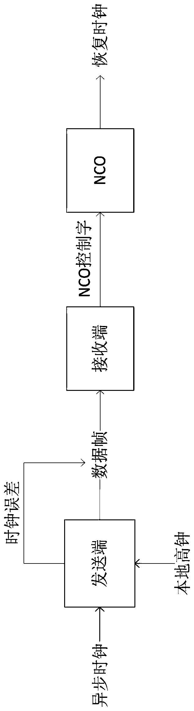
[0024] refer to Figure 1 to Figure 3 To further explain the present invention

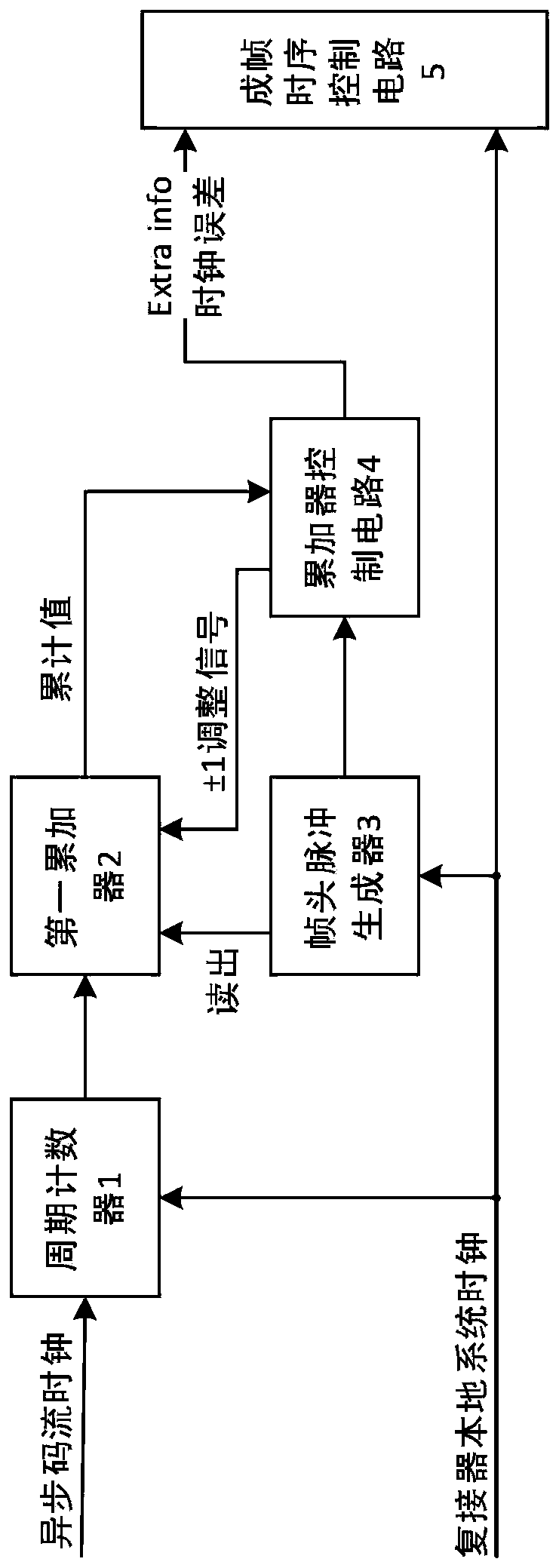
[0025] figure 2 It is a block diagram of the clock error generation principle at the sending end of the present invention, which includes each main processing module for generating the clock error.

[0026] Cycle counter 1 is used to sample and count the input asynchronous code stream clock according to the high clock of the local system, and obtain the cycle count value of the asynchronous code stream based on the local clock of the sending end. When each cycle of the asynchronous code stream clock ends, write the cycle count value to into the first accumulator 2;

[0027] The first accumulator 2 is used to read the accumulated value after receiving the read instruction;

[0028] The frame head pulse generator 3 is used for generating the pulse of marking the frame head position according to the high clock of the local system, and sends a read instruction to the first accumulator 2 when gener...


PUM


Abstract

The invention discloses a high-precision low-jitter clock recovery system, which can recover a low-jitter clock in wireless communication, does not have the problem of clock lock loss under the condition of multiple relays, and is suitable for the condition of multi-relay transmission in scattering networking. The main part is a distributed digital phase-locked loop. An input asynchronous code stream clock is sampled and counted through a sending end local system high clock, an asynchronous code stream period count value with the sending end local clock as the reference is obtained, so that aclock error is obtained, and a current asynchronous code stream clock can be recovered in real time at a tapping end according to the clock error value; different from the previous design, a distributed digital phase-locked loop is adopted, and the phase discrimination precision is improved by utilizing high clock counting, so that the clock jitter is reduced to a high clock period.

Description

technical field [0001] The invention relates to the problem of clock synchronization of sending and receiving in the field of signal multiplexing, discloses a high-precision and low-jitter clock recovery method, and realizes the recovery of the receiving end clock. Background technique [0002] The clock recovery algorithm is generated because, in order to save channel resources, the transmitting end generally only sends data signals but not the synchronous clock signal, so the synchronous clock signal must be extracted by the clock recovery algorithm at the receiving end. In the scattering fading channel, when the information is transmitted over a short distance, the clock can be extracted through the envelope. However, due to the time-varying and multipath effects of the scattering channel itself, the signal envelope will be distorted. If the existing clock recovery algorithm is used , when the rate is 64kb / s, only when the clock drift reaches 15.625 microseconds, the cloc...

Claims


Application Information

Patent Timeline
Patent Type & Authority Applications(China)
IPC IPC(8): H03L7/08H03L7/099
CPCH03L7/08H03L7/099
Inventor 赵靖远张涛孙柏昶李斐张子燕孟颢
Owner NO 54 INST OF CHINA ELECTRONICS SCI & TECH GRP
Features
  • R&D
  • Intellectual Property
  • Life Sciences
  • Materials
  • Tech Scout
  • Unparalleled Data Quality
  • Higher Quality Content
  • 60% Fewer Hallucinations
Learn More