Optical fiber transmission quality monitoring device for optical fiber composite overhead ground wire ice-melting through-flow process

An overhead ground wire and optical fiber transmission technology, which is applied in measurement devices, transmission monitoring/testing/fault measurement systems, transmission systems, etc., can solve problems such as low efficiency, inability to judge, and lack of optical fiber data for ice melting and flow process, etc. Achieve the effect of improving detection efficiency and ensuring reliability

Active Publication Date: 2020-07-03
ZHAOTONG POWER SUPPLYING BUREAU OF YUNNAN POWER GRID
View PDF9 Cites 1 Cited by
  • Summary
  • Abstract
  • Description
  • Claims
  • Application Information

AI Technical Summary

Problems solved by technology

However, it is limited to a short period of time and a small amount of laboratory test data, and there is a lack of effective optical fiber data basis for the actual ice-melting flow process. During the ice-melting flow process, the de-icing vibration of the optical cable, fiber core grease, coating layer, etc. Affects the transmission quality of optical cables, and it is impossible to judge whether the long-term deicing operation of optical fiber composite overhead ground wires will affect the quality of optical fiber transmission, and how much the impact will be
[0003] In order to clarify the impact of the long-term deicing operation of the optical fiber composite overhead ground line on the optical fiber transmission, it is necessary to collect a large amount of optical fiber data during the deicing flow process. The traditional manual measurement method is inefficient, and the traditional measurement equipment does not meet the function of automatically measuring the deicing process data. and lack of functionality to intelligently assess the impact of melting ice on fiber optic transmission

Method used


Image

  • Optical fiber transmission quality monitoring device for optical fiber composite overhead ground wire ice-melting through-flow process
  • Optical fiber transmission quality monitoring device for optical fiber composite overhead ground wire ice-melting through-flow process

Examples


Embodiment 1

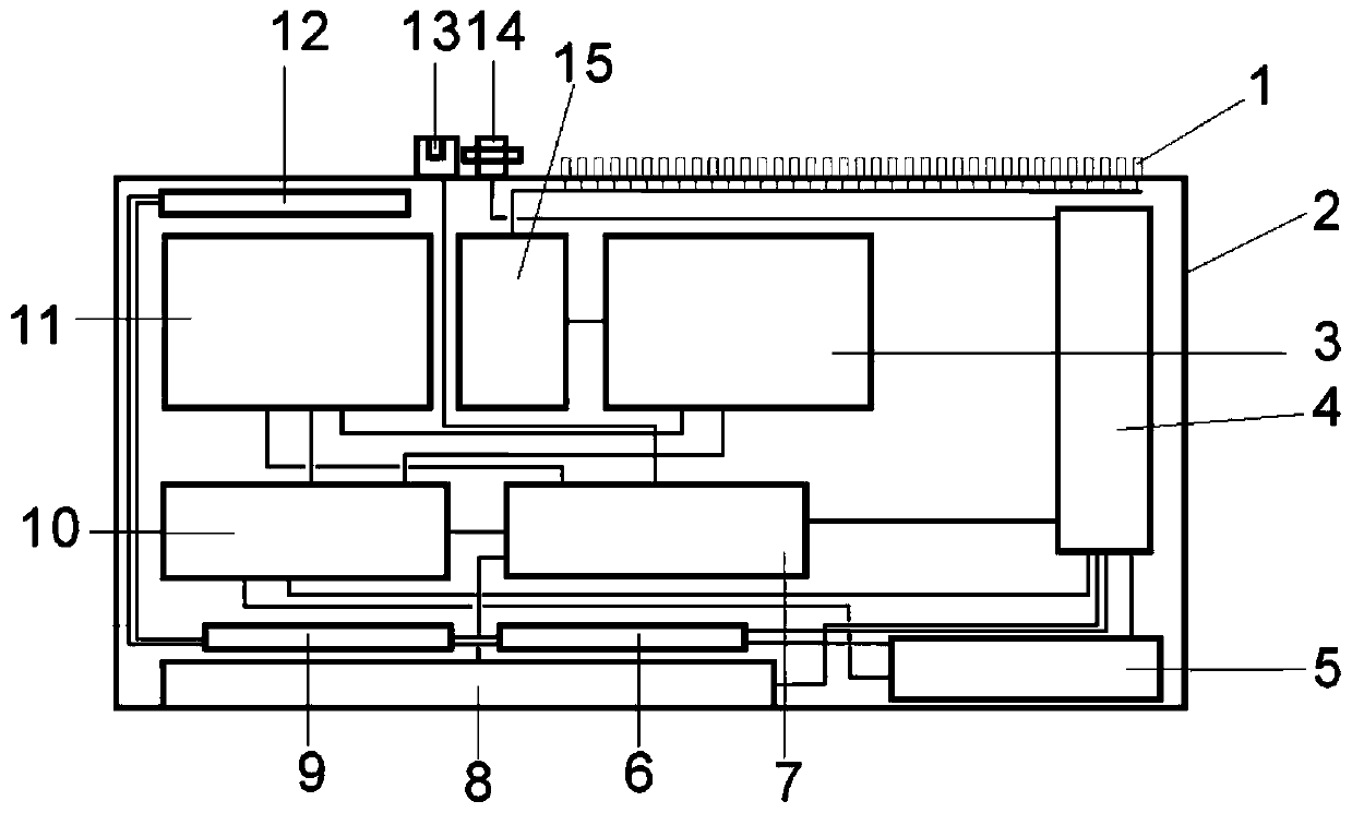
[0021] Embodiment 1: as figure 1 As shown, the optical fiber transmission quality monitoring device of the optical fiber composite overhead ground wire during ice melting and flow process includes 36-way flange panel 1, anti-static chassis 2, optical switch 3, power module 4, temperature control unit 5, fan I 6, industrial computer 7. Touch screen 8, fan II 9, main control circuit 10, light source module 11, fan III 12, converter 13, power switch 14, fiber coil 15; anti-static chassis 2 encapsulating optical switch 3, power module 4, temperature control unit 5 , fan Ⅰ6, industrial computer 7, fan Ⅱ9, main control circuit 10, light source module 11, fan Ⅲ12, fiber coil 15, 36-way flange panel 1, touch screen 8, converter 13, power switch 14 are set on the anti-static On the chassis 2; the 36-way flange panel 1 is installed and fixed on the back of the anti-static chassis 2, and the 36-way optical fiber output end of the optical switch 3 is coiled and fixed by the fiber reel 15 ...


PUM


Abstract

The invention discloses an optical fiber transmission quality monitoring device for an optical fiber composite overhead ground wire ice melting through-flow process. The optical fiber transmission quality monitoring device comprises 36 paths of flange panels, an anti-static case, an optical switch, a power supply module, a temperature control unit, a fan I, an industrial personal computer, a touchscreen, a fan II, a main control circuit, a light source module, a fan III, a converter, a power supply switch and a fiber winding disc, according to the optical fiber transmission quality monitoringdevice for the optical fiber composite overhead ground wire ice-melting through-flow process, the influence on the optical fiber transmission quality of a plurality of composite overhead ground wiresin the ice-melting through-flow process can be intelligently evaluated, the detection efficiency is improved, and the reliability of power communication is ensured.

Description

technical field [0001] The invention belongs to the field of on-line monitoring of power communication transmission quality, and in particular relates to an optical fiber transmission quality monitoring device for the deicing flow process of optical fiber composite overhead ground wires. Real-time online monitoring of streaming process transmission quality. Background technique [0002] The power grid enterprise has realized the ice melting of the optical fiber cable through the insulation transformation of the optical fiber composite overhead ground wire. Through theoretical and laboratory research, the relevant parameters of the optical fiber composite overhead ground wire melting ice flow process have been preliminarily determined, such as melting current, temperature rise, time, etc. . However, it is only limited to a short period of time and a small amount of laboratory test data, and there is a lack of effective data basis for the optical fiber in the actual ice-melti...

Claims


Application Information

Patent Timeline
Patent Type & Authority Applications(China)
IPC IPC(8): H04B10/079H04B10/07H04L29/08G01D21/02
CPCH04B10/079H04B10/07H04L67/025H04L67/125G01D21/02
Inventor 龙波马庆龙赵泽彪高兴芬周宗金李锐吴业鹏喻圆祥陈忠武杨益
Owner ZHAOTONG POWER SUPPLYING BUREAU OF YUNNAN POWER GRID
Why Eureka
Try Eureka