Reciprocating type branch variable-frequency and variable-amplitude vibration mechanism and operation method thereof
A variable-amplitude vibration and reciprocating technology, which is applied in the direction of picking machines, harvesters, agricultural machinery and implements, etc., can solve problems such as high cost, limited functions, and complex structures
- Summary
- Abstract
- Description
- Claims
- Application Information
AI Technical Summary
Problems solved by technology
Method used
Image
Examples
Embodiment 1
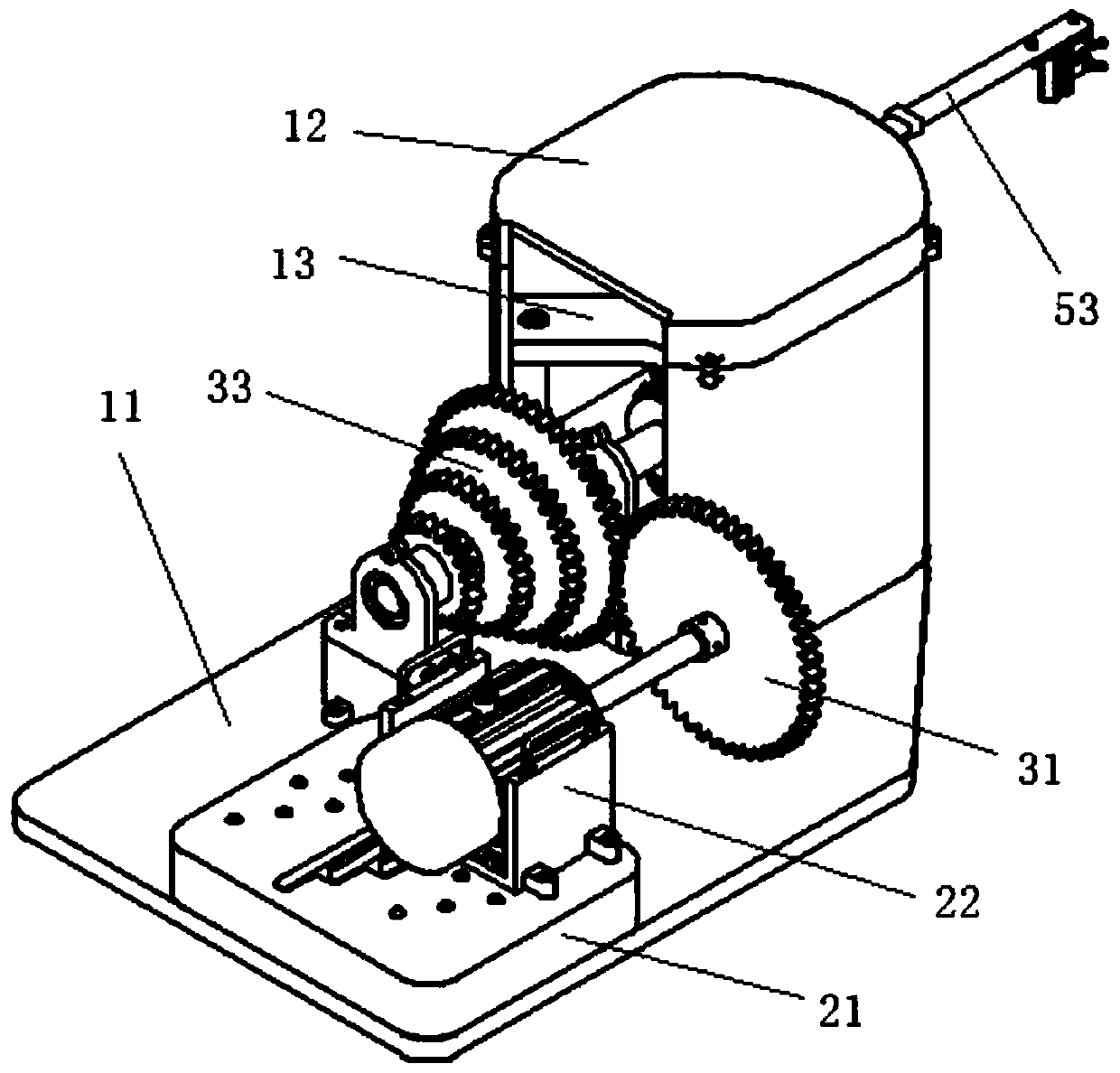
[0046] refer to image 3 , The reciprocating branch frequency variable amplitude vibration mechanism mainly includes a frame and a motor installed on it, a transmission mechanism, a vibration frequency adjustment mechanism, an amplitude adjustment mechanism and a branch fixing mechanism.
[0047] Wherein, the frame mainly includes the main body frame 11 of the frame, the top cover 12, the center cross bracket 13, etc., which are used to support the whole mechanism. The bearing of shaft 34 is positioned and supported.
[0048] refer to Figure 4 , the motor is installed at the bottom of the frame through the motor guide plate 21, the front end of the output shaft of the motor is fixed with a sleeve I, the transmission gear 31 is installed on the sleeve I, the horizontal transmission shaft 32 is arranged parallel to the output shaft of the motor, and the corresponding position on it is A sleeve II is fixed, and a plurality of meshing gears 33 with different transmission ratios...
Embodiment 2
[0064] This embodiment provides a method for operating a reciprocating branch frequency-variable-amplitude vibration mechanism, which is applied to the reciprocating branch frequency-variable-amplitude vibration mechanism in the above-mentioned embodiment 1. The operation method includes the following steps:
[0065] Step 1. Complete the installation of the reciprocating branch frequency-variable-amplitude vibration mechanism according to the preset frequency and amplitude. The adjustment of the preset frequency is realized by changing the gear train transmission ratio of the vibration frequency adjustment mechanism. The gear train transmission ratio range is 1:1 , 1:2, 1:3, 1:4; the adjustment of the preset amplitude is realized by changing the position where the power shaft of the reciprocating rod of the amplitude adjustment mechanism is fixed to the amplitude adjustment hole 52, and the amplitude adjustment range of the amplitude adjustment hole 52 is 5cm to 10cm ;
[0066...
Embodiment 3
[0070] A motor transmission and installation structure, which can be used to conveniently adjust the output transmission ratio of the motor.
[0071] refer to Figure 4~6 , the structure includes a motor, a motor guide plate 21, a motor output shaft, a horizontal transmission shaft 32, and a gear train. Wherein, the position of the motor can be adjusted and installed on the motor guide plate 21, the motor guide plate 21 is provided with a transmission ratio adjustment track 41 and a plurality of sets of motor positioning holes 42, the motor slider 22 is arranged below the motor, and the bottom of the motor slider 22 Two motor guide pins 23 are provided, and fixing bolts are provided at both ends. When the motor slide block 22 is moved to move the motor guide pin 23 to the designated transmission ratio position in the transmission ratio adjustment track 41, at this time, the motor can be fixed by tightening the fixing bolts to the corresponding motor positioning holes 42 below...
PUM
 Abstract
Description
Claims
Application Information
 - R&D
- Intellectual Property
- Life Sciences
- Materials
- Tech Scout
- Unparalleled Data Quality
- Higher Quality Content
- 60% Fewer Hallucinations
Browse by: Latest US Patents, China's latest patents, Technical Efficacy Thesaurus, Application Domain, Technology Topic, Popular Technical Reports.
© 2025 PatSnap. All rights reserved.Legal|Privacy policy|Modern Slavery Act Transparency Statement|Sitemap|About US| Contact US: help@patsnap.com


