Fixed bed up-flow reactor and application thereof

A reactor and fixed bed technology, applied in the field of upflow reactors, can solve problems such as blockage of distributors, increased bed pressure drop, adverse effects on the reaction process, etc.

Active Publication Date: 2020-07-07
CHINA PETROLEUM & CHEM CORP +1
View PDF15 Cites 0 Cited by
  • Summary
  • Abstract
  • Description
  • Claims
  • Application Information

AI Technical Summary

Problems solved by technology

Since the catalyst particles cannot pass through the small bed support gap, these particles are likely to block the distributor or bed support, resulting in uneven distribution of fluid, especially gas, which affects the distribution of fluid in the reactor and affects the reaction process. adversely affect
At the same time, it will also be accompanied by the wear and pulverization of the catalyst particles, resulting in a large amount of catalyst dust. These dusts move upward with the reaction materials, and clogging occurs on the surface of the screen or grid, resulting in a rapid increase in the pressure drop of the bed, affecting response start cycle

Method used


Image

  • Fixed bed up-flow reactor and application thereof
  • Fixed bed up-flow reactor and application thereof
  • Fixed bed up-flow reactor and application thereof

Examples


Embodiment 1

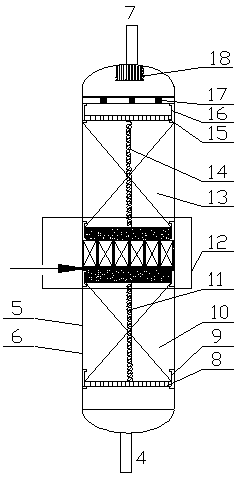
[0055] Using the upflow reactor of the present invention, the feedstock oil and hydrogen I are mixed with a conventional static mixer (model SV2.3 / 25-6.4-500), and then the mixture is introduced into the upstream as the reactor feed Type reactor (the diameter of the reactor is 100mm), the hydrogen II is introduced into the hydrogen inlet in the linked filter dust layer, where the mass ratio of hydrogen I to hydrogen II is 5:1; the direction of material flow in the reactor is as follows Sliding grid 100mm, first catalyst bed 600mm, linkage filter dust layer 260mm, second catalyst bed 800mm, upper sliding grid 80mm; lower sliding grid includes slideway and grille plate, slideway length is 100mm ; The upper sliding grille includes a slideway and a grille plate, the length of the slideway is 80mm; the linkage filter dust layer The linkage filter dust layer includes the upper linkage layer, the filter dust layer, and the lower linkage layer; the upper linkage layer includes the upper...

Embodiment 2

[0057] Using the upflow reactor of the present invention, the feedstock oil and hydrogen I are mixed with a conventional static mixer (model SV2.3 / 25-6.4-500), and then the mixture is introduced into the upstream as the reactor feed Type reactor (the diameter of the reactor is 100mm), the hydrogen II is introduced into the hydrogen inlet of the linked filter dust layer, where the mass ratio of hydrogen I to hydrogen II is 3:1; the flow direction of the materials in the reactor is as follows Sliding grid 100mm, first catalyst bed 500mm, linkage filter dust layer 200mm, second catalyst bed 600mm, upper sliding grid 80mm, gland 100mm; lower sliding grid includes slideways and grid plates, sliding The length of the channel is 100mm; the upper sliding grille includes a slideway and a grille plate, and the length of the slideway is 80mm; the linkage filter dust layer The linkage filter dust layer includes the upper linkage layer, the filter dust layer, and the lower linkage layer; Th...


PUM

PropertyMeasurementUnit
lengthaaaaaaaaaa
heightaaaaaaaaaa
heightaaaaaaaaaa

Abstract

The invention discloses a fixed bed up-flow reactor and application thereof. The reactor comprises a reactor shell, and a lower sliding grid, a first catalyst bed layer, a linkage type filtering dustaccumulation layer, a second catalyst bed layer and an upper sliding grid are arranged in the reactor shell in the material flowing direction; the linkage type filtering dust accumulation layer is fixedly connected with the upper sliding grid and the lower sliding grid through supporting rods, a reaction material inlet is formed in the bottom of the reactor shell, and a reaction material outlet isformed in the top of the reactor shell; the reactor is internally provided with a linkage type filtering dust accumulation layer, so that the motion abrasion among catalyst particles can be effectively reduced, the service life of the catalyst is prolonged, the catalyst dust is continuously removed in the reaction process, the reaction uniformity is improved, the rising of the pressure drop of acatalyst bed layer is greatly slowed down, and the long-period stable operation of the reactor is maintained.

Description

Technical field [0001] The invention belongs to the field of petrochemical equipment and relates to an upflow reactor and its application. Background technique [0002] In the petrochemical industry, the hydrogenation process is an important technical means for processing distillate oil and secondary processing oil. Through hydrogenation, the sulfur, nitrogen, metal, colloid, carbon residue and other impurities in the oil can be effectively treated. Removal and hydrogenation of unsaturated hydrocarbons into saturated hydrocarbons. According to the reactor type, the hydrogenation process can be divided into fixed bed hydrogenation process, suspended bed hydrogenation process, and fluidized bed hydrogenation process. Among them, the fixed bed hydrogenation process is the most widely used. [0003] According to the feeding method of the fixed bed reactor, it can be divided into two methods: up-flow type, that is, down-feeding, and down-flow type, that is, up-feeding fixed-bed reactor...

Claims


Application Information

Patent Timeline
Patent Type & Authority Applications(China)
IPC IPC(8): B01J8/04C10G49/00
CPCB01J8/0446B01J8/0492B01J2208/00884C10G49/00C10G2300/4006C10G2300/4012
Inventor 周嘉文杨秀娜阮宗琳王昊晨姜阳崔国英关明华
Owner CHINA PETROLEUM & CHEM CORP
Why Eureka
Try Eureka