Assembly line marking equipment

A marking equipment and assembly line technology, applied in welding equipment, welding equipment, laser welding equipment, etc., can solve the problems of position deviation, different heights, and circuit board inclination during marking

Active Publication Date: 2020-07-07
NANJING NIEBO INTERNET OF THINGS TECH CO LTD
View PDF4 Cites 3 Cited by
  • Summary
  • Abstract
  • Description
  • Claims
  • Application Information

AI Technical Summary

Problems solved by technology

[0003] Based on the inventor's discovery above, the existing assembly line marking equipment mainly has the following disadvantages, such as: when marking an integrated circuit board, since the components are all arranged on the upper end of the circuit board, it is necessary to place the marking on the upper en

Method used


Image

  • Assembly line marking equipment
  • Assembly line marking equipment
  • Assembly line marking equipment

Examples


Embodiment 1

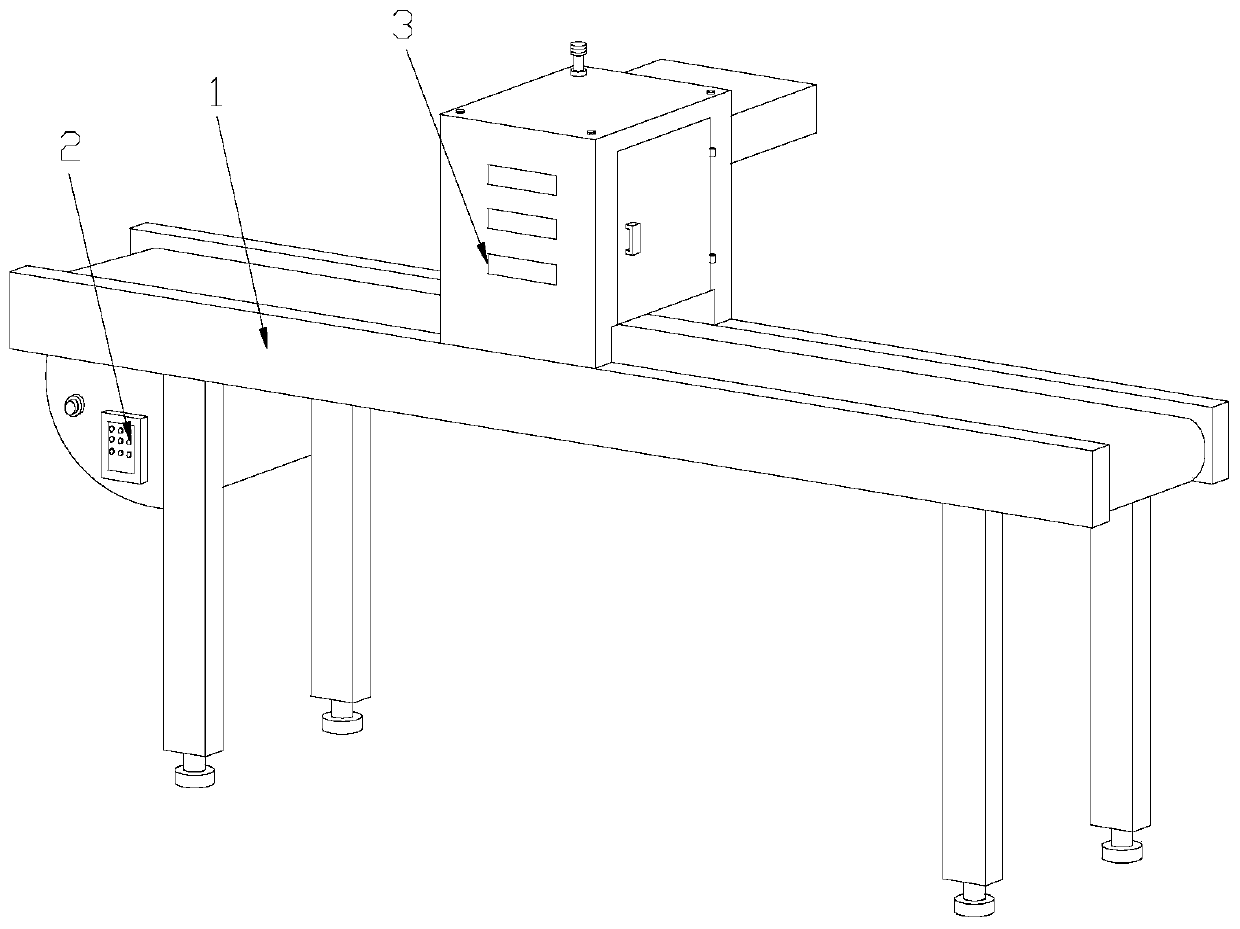
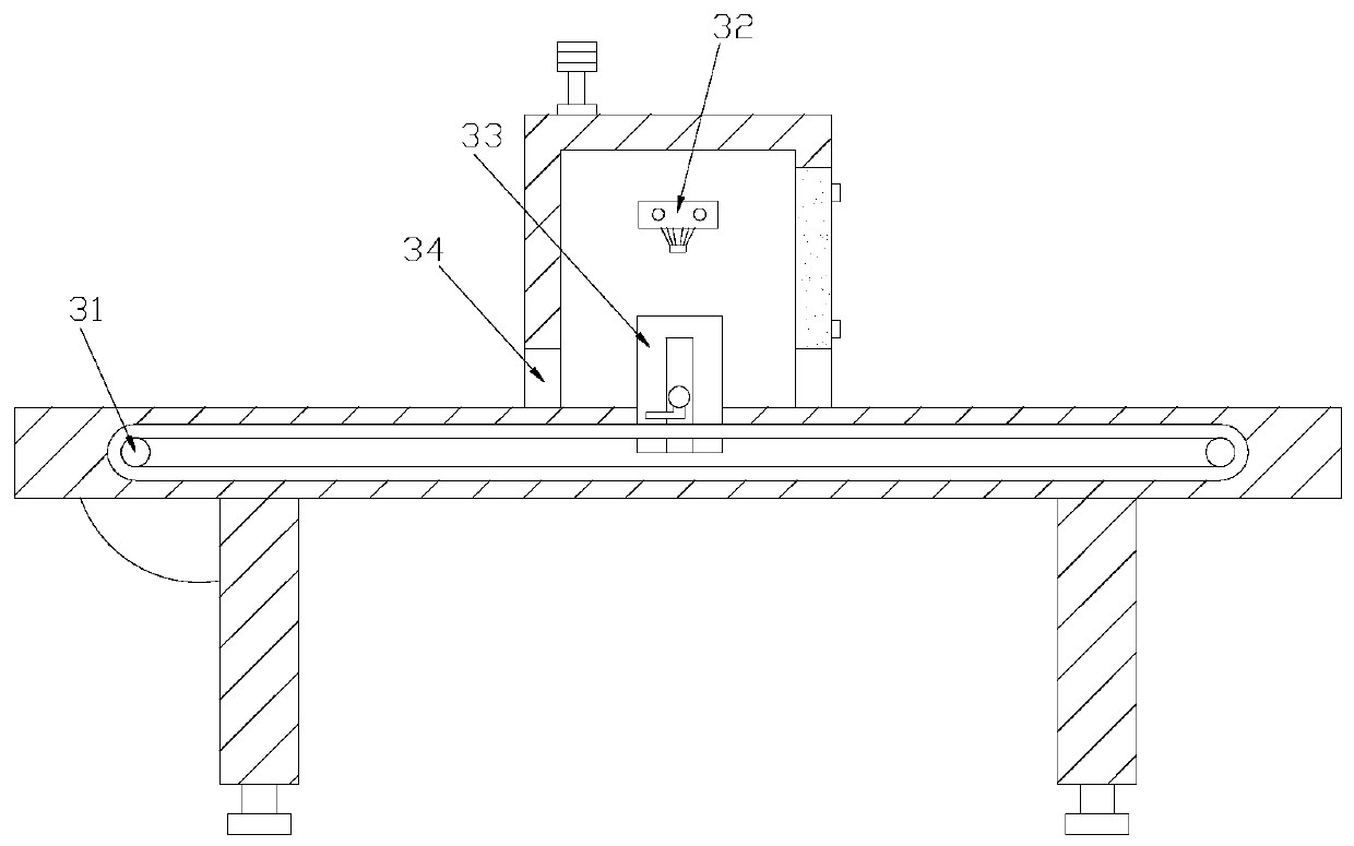
[0027] Example 1: Please refer to Figure 1-Figure 5 , the specific embodiment of the present invention is as follows: its structure comprises bracket 1, control box 2, marking box 3, the bottom of described bracket 1 is welded with control box 2, and described marking box 3 is installed in the top middle of bracket 1, The marking box 3 includes a conveyor belt 31, a laser emitter 32, a clamping device 33, and a material opening 34. The conveyor belt 31 is installed on the inside of the bracket 1, and the laser emitter 32 is embedded in the marking box 3. At the top, the clamping device 33 is installed at the inner bottom of the marking box 3 , and the material opening 34 is arranged on both sides of the bottom of the marking box 3 .

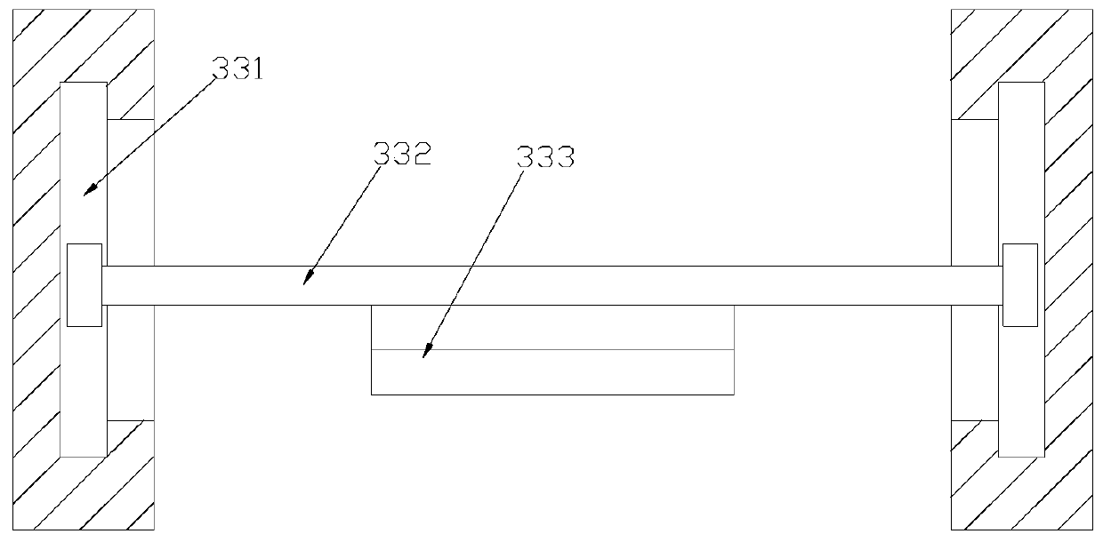
[0028] The clamping device 33 includes a slide groove 331, a support rod 332, and a clamp 333. The support rod 332 is installed in the slide groove 331, and the clamp 333 is welded in the middle of the bottom of the support rod 332. The support ...

Embodiment 2

[0032] Example 2: Please refer to Figure 6-Figure 8 The specific embodiments of the present invention are as follows: the guide block a23 is composed of a guide body b1, a slot b2, a contact block b3, and a pressing device b4, the guide body b1 is triangular in shape, and the slot b2 is arranged on the guide body On the slope of b1, there are three contact blocks b3, the contact blocks b3 are horizontally arranged at the bottom of the guide body b1, the pressing device b4 is installed at the rear end of the guide body b1, and the clamping groove b2 is triangular There are three card slots b2, and the card slots b2 are horizontally arranged on the slope of the guide body b1, which is beneficial to block the circuit board on the guide roller a22 through the card slot b2, and prevent the circuit board from sliding down. Condition.

[0033] The pressing device b4 is composed of an engaging groove b41, a second spring b42, and a connecting block b43. The top end of the engaging g...


PUM


Abstract

The invention discloses assembly line marking equipment. The assembly line marking equipment structurally comprises a support, a control box and a marking box. The control box is welded to the bottomof the support. The marking box is installed right in the middle of the top of the support and comprises a conveying belt, a laser transmitter, a clamping device and a material passing port. The clamping device comprises a sliding groove, a supporting rod and a clamp. The clamp comprises a groove, a guiding device and a downward pressing plate. The guiding device is composed of a connecting rod, awheel, a guiding block, a telescopic rod and a first spring. The triangular guiding block is used for guiding a circuit board to the upper end of the wheel, the wheel is driven by the conveying beltto rotate by itself, accordingly, the circuit board arranged on the wheel can be driven to move, the side end of the circuit board can be fixed to the guiding device, the downward pressing plate downwards presses and clamps the circuit board, finally, the supporting rod drives the clamp to move upwards, the circuit board can be fixed to the clamp, and the situation of inclination of the circuit board during marking is avoided.

Description

technical field [0001] The invention relates to the field of assembly line equipment, in particular to an assembly line marking equipment. Background technique [0002] Marking machines are used in various factories, because each electronic component, integrated circuit, electrical appliance, mobile phone communication, hardware product, tool and other parts have their own brand, so it is necessary to mark the outer surface of the part. The permanent mark is used as a mark, and the general marking machine uses laser marking, which is stable and fast. [0003] Based on the inventor's discovery above, the existing assembly line marking equipment mainly has the following disadvantages, such as: when marking an integrated circuit board, since the components are all arranged on the upper end of the circuit board, it is necessary to place the marking on the upper end of the circuit board. Marking on the back of the circuit board, and the heights of the capacitors, resistors, trio...

Claims


Application Information

Patent Timeline
IPC IPC(8): B23K26/362B23K26/70B23K37/04B23K101/42
CPCB23K26/362B23K37/0443B23K26/702B23K2101/42
Inventor 戈建国
Owner NANJING NIEBO INTERNET OF THINGS TECH CO LTD
Why Eureka
Try Eureka