Mobile equipment positioning method, device and system and mobile equipment

A technology for mobile devices and positioning systems, which can be used in measurement devices, instruments, navigation, etc., and can solve the problems of low robustness and low positioning accuracy.

Active Publication Date: 2020-07-07
浙江菜鸟供应链管理有限公司
View PDF10 Cites 0 Cited by
  • Summary
  • Abstract
  • Description
  • Claims
  • Application Information

AI Technical Summary

Problems solved by technology

[0005] This application provides a mobile device positioning system to solve the problems of low positioning accuracy and low robustness existing in the prior art

Method used


Image

  • Mobile equipment positioning method, device and system and mobile equipment
  • Mobile equipment positioning method, device and system and mobile equipment
  • Mobile equipment positioning method, device and system and mobile equipment

Examples


no. 1 example

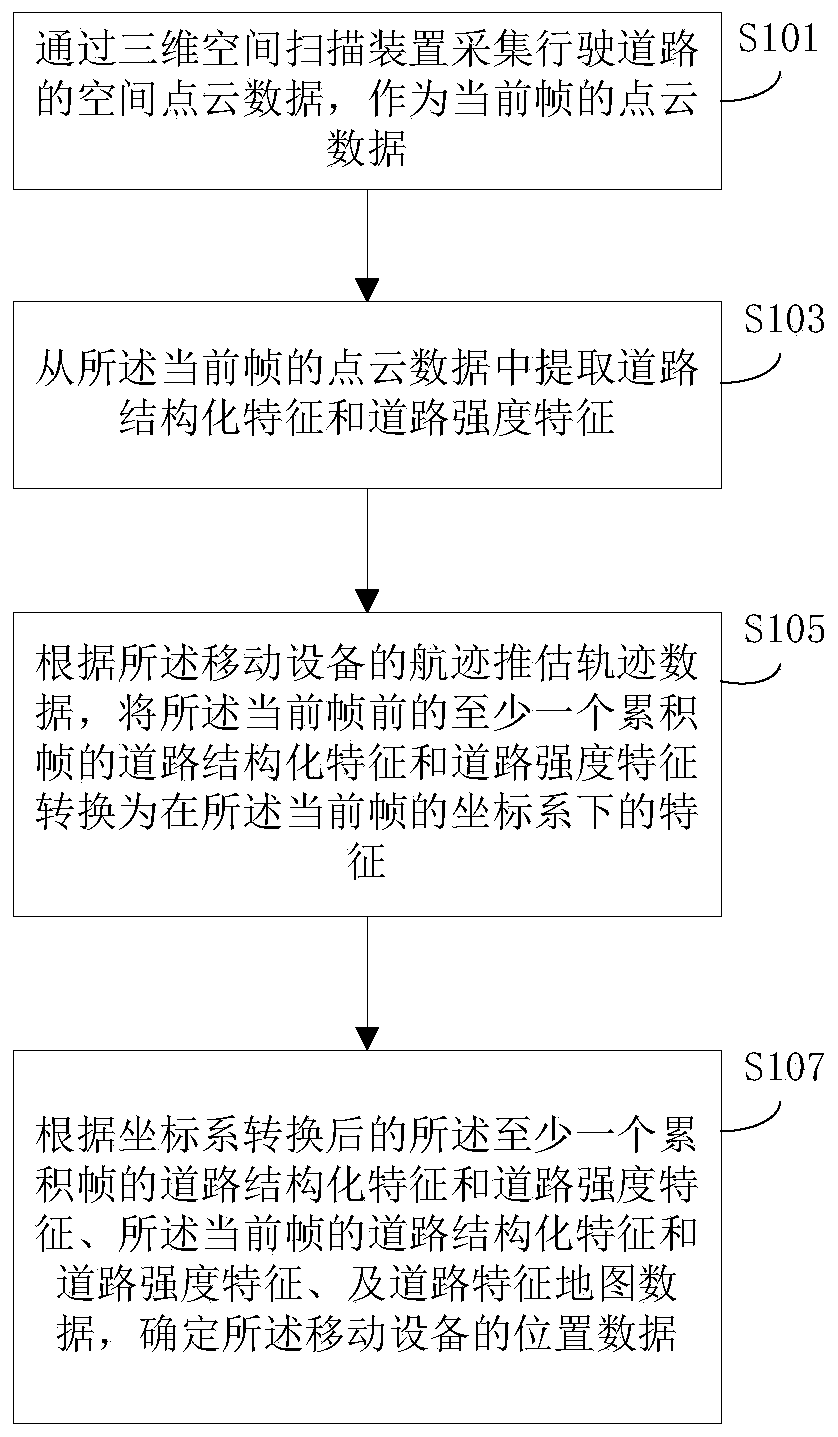
[0108] Please refer to figure 1 , which is a flow chart of an embodiment of a method for locating a mobile device provided in the present application. The execution body of the method includes a device for locating a mobile device, and the device can be deployed on a mobile device. A mobile device positioning method provided by this application includes:

[0109] Step S101: Collect the spatial point cloud data of the driving road by the three-dimensional space scanning device as the point cloud data of the current frame.

[0110] In the method provided in the embodiment of the present application, when the vehicle is running, the three-dimensional space scanning device installed on the vehicle acquires the spatial coordinates of each sampling point on the surface of the object in the space around the road, and obtains a set of points, each The massive point data obtained in the second scan is called a frame of point cloud (Point Cloud) data. In this embodiment, the frame of p...

no. 2 example

[0170] Please see Figure 9 , which is a schematic diagram of an embodiment of the device for locating mobile equipment of the present application. Since the device embodiment is basically similar to the method embodiment, the description is relatively simple, and for relevant parts, refer to the part of the description of the method embodiment. The device embodiments described below are illustrative only.

[0171] The present application additionally provides a positioning device for mobile equipment, including:

[0172] The point cloud data collection unit 901 is used to collect the spatial point cloud data of the driving road through the three-dimensional space scanning device as the point cloud data of the current frame;

[0173] The current frame road feature extraction unit 903 is configured to extract road structural features and road strength features from the point cloud data of the current frame;

[0174] The accumulated frame road feature conversion unit 905 is c...

no. 3 example

[0187] Please refer to Figure 12 , which is a schematic diagram of a mobile device embodiment of the present application. Since the device embodiment is basically similar to the method embodiment, the description is relatively simple, and for related parts, please refer to part of the description of the method embodiment. The device embodiments described below are illustrative only.

[0188] A mobile device in this embodiment includes: a three-dimensional space scanning device 1201 , a processor 1202 and a memory 1203 .

[0189] The memory is used to store the program for realizing the positioning method of the mobile device. After the device is powered on and runs the program of the positioning method for the mobile device through the processor, the following steps are performed: the spatial points of the driving road are collected by the three-dimensional space scanning device Cloud data, as the point cloud data of the current frame; extracting road structural features an...


PUM


Abstract

The invention discloses a mobile equipment positioning system, method and device and mobile equipment. The method comprises the following steps: using a three-dimensional space scanning device to collect spatial point cloud data of a driving road, extracting road structured features and road strength features from the point cloud data, and estimating track data according to the track of the mobileequipment; converting the road structured features and the road strength features of the accumulated frame before the current frame into features under a coordinate system of the current frame; and determining the position data of the mobile equipment according to the road structural features and the road strength features of the accumulated frame, the road structural features and the road strength features of the current frame and the road feature map data after coordinate system conversion. By the adoption of the processing mode, the road feature expression capacity is enhanced, and the problem that positioning cannot be conducted when the road structural features or the road strength features cannot be effectively obtained is solved; therefore, the positioning precision and robustnesscan be effectively improved.

Description

technical field [0001] The present application relates to the technical field of unmanned driving, and specifically relates to a positioning method, device and system for mobile equipment, and mobile equipment. Background technique [0002] Autonomous driving technology is a major research hotspot in the field of automation in recent years. One of the core technologies of autonomous driving technology is the high-precision positioning of vehicles. In the process of automatic driving, it is usually necessary to achieve centimeter-level accuracy for the position of the vehicle itself to ensure the correctness of automatic driving and driving safety. [0003] At present, a typical vehicle localization method is the laser point cloud localization method, and its processing process is as follows. Laser point cloud positioning generally requires pre-made maps (such as 2D or 3D maps), and then matches the real-time point cloud with the map while the vehicle is driving, calculates ...

Claims


Application Information

Patent Timeline
Patent Type & Authority Applications(China)
IPC IPC(8): G01C21/20G01C21/30
CPCG01C21/005G01C21/20G01C21/30
Inventor 邓欢军张硕
Owner 浙江菜鸟供应链管理有限公司
Why Eureka
Try Eureka