Check patentability & draft patents in minutes with Patsnap Eureka AI!

Method for improving resolution of laser ultrasonic visual image

An image resolution, laser ultrasound technology, applied in image analysis, image enhancement, analysis of solids using sonic/ultrasonic/infrasonic waves, etc.

Pending Publication Date: 2020-07-07
INST OF METAL RESEARCH - CHINESE ACAD OF SCI
View PDF4 Cites 5 Cited by
  • Summary
  • Abstract
  • Description
  • Claims
  • Application Information

AI Technical Summary

Problems solved by technology

It can be seen that this method not only does not perform low-frequency coefficient processing on the original image, but directly uses the low-resolution image as the low-frequency sub-band and interpolates the high-frequency part, which adds extra high-frequency energy, which will make the high-frequency sub-band The detailed information in the band produces deviations, which affects the reconstruction quality

Method used


Image

  • Method for improving resolution of laser ultrasonic visual image
  • Method for improving resolution of laser ultrasonic visual image
  • Method for improving resolution of laser ultrasonic visual image

Examples


Embodiment Construction

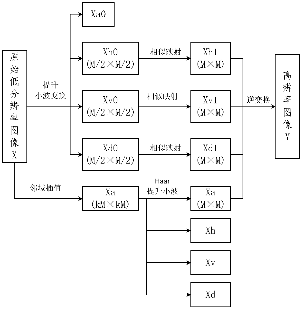
[0026] The present invention will be further described in detail below in conjunction with the accompanying drawings and embodiments.

[0027] The laser ultrasonic non-destructive testing system uses a Q-switched Nd:YAG pulsed laser (pulse width 10ns, repetition rate up to 1000Hz, pulse energy up to 10mJ) to excite the laser, and controls the laser point to scan on the workpiece through the deflection mirror. Type acoustic emission sensor (resonance frequency 500-2000KHz, size Φ6mm) receives ultrasonic signals, after amplification and filtering (amplifier gain 60dB), synchronous trigger signal acquisition card (sampling frequency 16.66MHz, sampling depth 2000 points) collects data and stores them in the computer. Image display with ultrasound propagation visualization software.

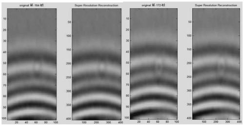
[0028] The above-mentioned system is used to carry out detection experiments on large-diameter pipe wall welds. The size of the laser ultrasonic detection area is 47mm×94mm. The laser point is contro...


PUM


Abstract

The invention discloses a method for improving the resolution of a laser ultrasonic visual image. The method is characterized by comprising the following steps: direct neighborhood interpolation is carried out on the original image; according to the method, Haar wavelet decomposition is carried out after the resolution is doubled, a high-frequency sub-band obtained by carrying out Haar wavelet decomposition on a low-resolution image is used as a low-frequency part, the corresponding high-frequency part is set to be zero, inverse wavelet transformation is carried out, and then the high-frequency sub-band with the resolution doubled is obtained. Meanwhile, the detail coefficients after wavelet transformation are subjected to mapping processing, a new detail coefficient image is obtained, thedetail image contains more detail information compared with an original detail coefficient image, and deviation generated by high-frequency sub-band detail information in an existing processing method can be made up for. And finally, wavelet inverse transformation is carried out by combining the high-frequency sub-band and the three mapped detail coefficients to obtain a new image. Through the method, the imaging quality can be improved, so that the defect information can be better presented.

Description

technical field [0001] The invention belongs to the technical field of laser ultrasonic non-destructive testing, and relates to a method for improving the quality of laser ultrasonic visual imaging and improving the defect identification ability. Background technique [0002] The laser ultrasonic visualization image is limited by the stepping accuracy of the detection mechanism, which often makes the resolution of the obtained detection image unsatisfactory, and it is impossible to obtain a higher resolution detection image. The pixel density is low, which brings great challenges to the quantitative measurement of pitting defects. Therefore, a super-resolution reconstruction method for laser ultrasound visualization images based on wavelet analysis is proposed. Wavelet analysis is a time (space)-frequency domain analysis method that can achieve localization in the time (space) domain or frequency domain. Mechanisms of Human Vision. The existing image resolution improvement...

Claims


Application Information

Patent Timeline
IPC IPC(8): G06T3/40G06T5/10G06T5/20G01N29/24G01N29/06G01N29/44
CPCG06T3/4076G06T5/10G06T5/20G01N29/2418G01N29/0654G01N29/069G01N29/44G06T2207/20064G06T2207/10136G01N2291/0289
Inventor 张博张宝俊张双楠李经明刘畅刘芳蔡桂喜
Owner INST OF METAL RESEARCH - CHINESE ACAD OF SCI
Features
  • R&D
  • Intellectual Property
  • Life Sciences
  • Materials
  • Tech Scout
  • Unparalleled Data Quality
  • Higher Quality Content
  • 60% Fewer Hallucinations
Learn More