Earthquake protection bed with high structural strength

A technology for structural strength and fixed bottom plate, which is applied in the direction of beds, bed frames, and other seating furniture, etc. It can solve the problems of internal casualties, long-term danger of personnel, and easily damaged protective devices, so as to achieve internal space safety and protect life safety , Enhance the effect of structural strength

Inactive Publication Date: 2020-07-10
叶长水
View PDF2 Cites 3 Cited by
  • Summary
  • Abstract
  • Description
  • Claims
  • Application Information

AI Technical Summary

Problems solved by technology

[0007] Aiming at the deficiencies of the prior art, the present invention provides an earthquake protection bed with high structural strength, which solves the problem that the earthquake protection devices currently used are usually planar structures. When an earthquake occurs, falling objects will b

Method used


Image

  • Earthquake protection bed with high structural strength
  • Earthquake protection bed with high structural strength
  • Earthquake protection bed with high structural strength

Examples


Embodiment 1

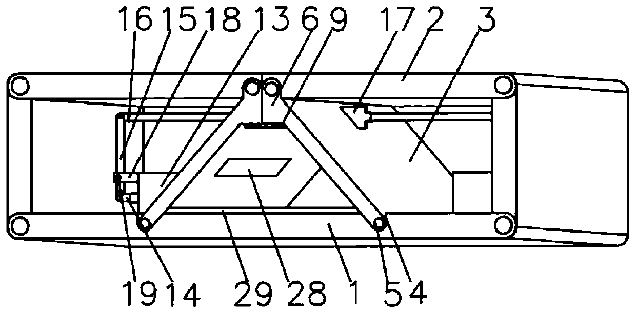
[0035] see Image 6 , the present invention provides a technical solution: an earthquake protection bed with high structural strength, including a fixed seat 13 fixedly connected to the top of the fixed base plate 1, a hydraulic pump 14 fixedly connected to one side of the fixed seat 13, and one end of the piston rod of the hydraulic pump 14 A connecting rod 15 is connected in rotation, and the end of the connecting rod 15 away from the hydraulic pump 14 is connected with a pull rod 16 in rotation. 3 fixedly connected, the top of the fixed seat 13 is fixedly connected with a bracket 18, the inner wall of the bracket 18 is fixedly connected with a support bolt 19, the support bolt 19 runs through the connecting rod 15 and is connected with the connecting rod 15 in rotation, the position of the supporting bolt 19 is located on the connecting rod 15 close to One end of the hydraulic pump 14, the contraction of the hydraulic pump 14 drives one end of the connecting rod 15 to rotat...

Embodiment 2

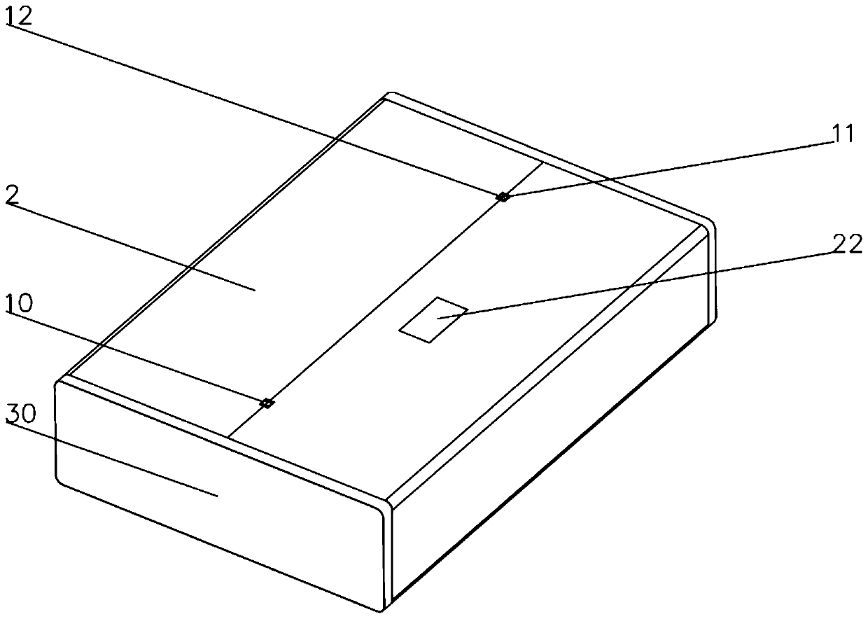
[0037] see Figure 1-5 , on the basis of Embodiment 1, the present invention provides a technical solution: a high-strength earthquake protection bed, including a fixed base plate 1, and a top cover 2 is rotatably connected to both ends of the fixed base plate 1, and the top cover 2 The bottom of one end away from the fixed bottom plate 1 is rotatably connected with a slanting support plate 3 , and the top of the fixed bottom plate 1 is provided with a rotating groove 4 , and the inner wall of the rotating groove 4 is fixedly connected with a rotating pin 5 , and the rotating pin 5 runs through the slanting supporting plate 3 One end away from the top cover 2 is connected to the inclined support plate 3 in rotation. The end of the inclined support plate 3 close to the top cover 2 is fixedly connected with a locking platform 6, and the bottom of the locking platform 6 is provided with a locking hole 7. The inner wall of the locking hole 7 is provided with a fixing hole 8, the i...


PUM


Abstract

The invention discloses an earthquake protection bed with high structural strength, which comprises a fixed bottom plate, top covers are rotationally connected to the two ends of the fixed bottom plate. The bottom of the end, away from the fixed bottom plate, of the top cover is rotationally connected with an inclined supporting plate. A rotating groove is formed in the top of the fixed bottom plate; a rotating bolt is fixedly connected to the inner wall of the rotating groove; the rotating bolt penetrates through the end, away from the top cover, of the inclined supporting plate and is rotationally connected with the inclined supporting plate. A locking table is fixedly connected to the end, close to the top cover, of the inclined supporting plate, a locking hole is formed in the bottom of the locking table, a fixing hole is formed in the inner wall of the locking hole, a lock catch device is slidably connected to the inner wall of the locking hole, and a hinge groove is formed in thetop of the end, away from the fixing bottom plate, of the top cover. The earthquake protection bed with high structural strength is safer and more comfortable to use, can effectively protect the lifesafety of users, and is simple in opening operation and higher in opening speed.

Description

technical field [0001] The invention relates to the technical field of natural disaster protection, in particular to an earthquake protection bed with high structural strength. Background technique [0002] Natural disasters refer to natural phenomena that cause harm to human existence or damage the living environment of human beings, including drought, high temperature, low temperature, cold wave, flood, mountain torrent, typhoon, tornado, flame tornado, hail, wind hail, frost, heavy rain, snowstorm, Freezing rain, heavy fog, strong wind, freezing, haze, smog, earthquake, tsunami, mudslide, floating dust, blowing sand, sandstorm, lightning, thunderstorm, ball lightning, volcanic eruption, etc. [0003] According to the Chinese patent CN106308196B, it includes a front bed frame 7, a rear bed frame 2, a bottom plate 5, and a rotating plate 4. The two ends of 4 are respectively fixed on the front bed frame 7 and the rear bed frame 2, the front bed frame 7 is a square cavity s...

Claims


Application Information

Patent Timeline
IPC IPC(8): A47C19/02A47C21/04A47C31/00
CPCA47C19/021A47C21/048A47C31/002
Inventor 叶长水
Owner 叶长水
Why Eureka
Try Eureka