Improved numerically controlled lathe

An improved technology for CNC lathes, applied in the field of CNC lathes, can solve the problems of reducing the quality of processed parts, deformation of opening and closing doors, interference, etc., and achieve the effect of protecting the sealing effect, avoiding deformation, and facilitating reuse

Pending Publication Date: 2020-07-10
张勇
View PDF12 Cites 4 Cited by
  • Summary
  • Abstract
  • Description
  • Claims
  • Application Information

AI Technical Summary

Problems solved by technology

[0005] In view of the deficiencies in the prior art, the purpose of the present invention is to provide an improved CNC lathe to solve the problem that when the CNC lathe is performing processing operations, the metal debris generated is easy to accumulate and adsorb on the surface of the tool or the machined parts, causing the tool to be broken. Interference with metal debris during the processing of the parts makes the surface of the processed parts not meet the requir

Method used


Image

  • Improved numerically controlled lathe
  • Improved numerically controlled lathe
  • Improved numerically controlled lathe

Examples


Example Embodiment

[0031] Embodiment one

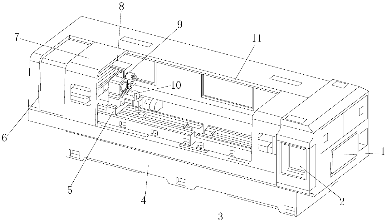
[0032] see figure 1 , the present invention provides a technical solution for an improved numerical control lathe: an improved numerical control lathe, the structure of which includes an adsorption plate 1, a control panel 2, a slide rail 3, a car body 4, a moving slider 5, a protective device 6, a switch door 7. Fixing seat 8, blowing device 9, knife holder 10, slideway 11, the rear end of the adsorption plate 1 is closely attached to the inside of the car body 4, and the upper right end of the car body 4 is provided with a control panel 2, the The left and right sides of the front end of the car body 4 are provided with switch doors 7, and the switch doors 7 are slidably connected to the slideway 11. The slideway 11 is fixedly installed on the car body 4, and protective devices are provided on both sides of the slideway 11. 6. The protection device 6 is connected to the switch door 7 through the slideway 11, one end of the protection device 6 is f...

Example Embodiment

[0039] Embodiment two

[0040] see figure 1 , the present invention provides a technical solution for an improved numerical control lathe: an improved numerical control lathe, the structure of which includes an adsorption plate 1, a control panel 2, a slide rail 3, a car body 4, a moving slider 5, a protective device 6, a switch door 7. Fixing seat 8, blowing device 9, knife holder 10, slideway 11, the rear end of the adsorption plate 1 is closely attached to the inside of the car body 4, and the upper right end of the car body 4 is provided with a control panel 2, the The left and right sides of the front end of the car body 4 are provided with switch doors 7, and the switch doors 7 move left and right on the slideway 11. The slideway 11 is fixedly installed on the car body 4, and the two sides of the slideway 11 are provided with A protective device 6, the protective device 6 is connected with the switch door 7 through a slideway 11, one end of the protective device 6 is...


PUM


Abstract

The invention discloses an improved numerically controlled lathe structurally comprising an adsorption plate, an operation panel, a slide rail, a lathe body, a movable slide block, a protective device, a switch door, a fixed seat, an air blowing device, a tool rest and a slide way. After improvement, the air blowing device is operated by a controller, and the air is conveyed into a connecting ringthrough a guide pipe, so that an air blowing port uniformly blows the air out, metal scraps adsorbed on the surface of a tool or a machined part are blown onto the adsorption plate, and the tool is prevented from being interfered with by the metal scraps in the machining process of the part; when the lathe opens the switch door after processing the part, the switch door slides to left and right sides due to inertia; and when the switch door touches a chucking board, the switch door is magnetically and fixedly adsorbed on the chucking board through a magnetic adsorption ball under the magneticaction, and the switch door is protected through cooperation of a protective cover and a buffering bullet piece, such that the inner side of the switch door is avoided from deforming, the switch doorcan be normally closed, and the sealed effect of protecting the switch door is achieved.

Description

technical field [0001] The invention relates to the field of numerically controlled lathes, in particular to an improved numerically controlled lathe. Background technique [0002] With the rapid development of social economy, CNC lathes are one of the most widely used CNC machine tools at present. CNC lathes are generally used in production workshops. CNC machine tools automatically process the processed parts according to the pre-programmed processing programs. CNC machine tools increase the processing speed and accuracy of workpieces and increase productivity. When the CNC lathe is processing, it needs to be improved: [0003] 1. When the CNC lathe is performing processing operations, the metal debris generated is easy to accumulate and adsorb on the surface of the tool or the processed parts, causing the tool to be interfered by metal debris during the processing of the parts, making the surface of the processed parts unsuitable for use. Requirements, greatly reducing ...

Claims


Application Information

Patent Timeline
IPC IPC(8): B23B25/00B23Q11/00B23Q11/08B23Q1/00B24B27/00B24B55/06B24B55/00
CPCB23B25/00B23Q1/0045B23Q11/0032B23Q11/0042B23Q11/005B23Q11/08B24B27/0092B24B55/00B24B55/06
Inventor 张勇
Owner 张勇
Why Eureka
Try Eureka