
Quick cutting device for cemented carbide round rod

A fast cutting, cemented carbide technology, used in auxiliary devices, welding/cutting auxiliary equipment, metal processing equipment, etc. Accurate effect of speed and cutting length

Inactive Publication Date: 2020-07-10
ZHUZHOU JINGGONG CEMENTED CARBIDE
View PDF0 Cites 1 Cited by
  • Summary
  • Abstract
  • Description
  • Claims
  • Application Information

AI Technical Summary

Problems solved by technology

At present, the cutting of alloy rods mainly adopts manual cutting. Due to the great influence of human factors on the size of the rods, the work efficiency is low and the yield rate is low; in the process of rapid development of today's technology, how to achieve high-speed and precise cutting of cemented carbide round rods And it has the process of automatic cutting to achieve rapid production, which is an urgent problem to be solved

Method used


Image

  • Quick cutting device for cemented carbide round rod
  • Quick cutting device for cemented carbide round rod
  • Quick cutting device for cemented carbide round rod

Examples


Embodiment Construction

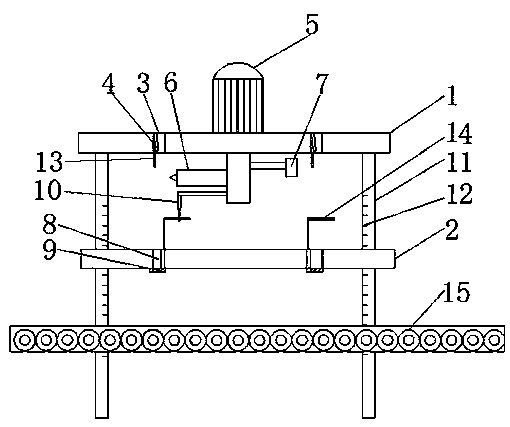
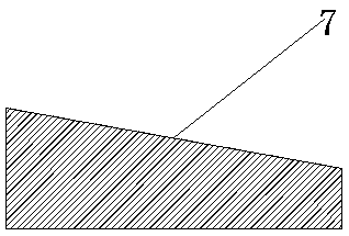
[0018] see Figure 1~Figure 3 , figure 1 It is a structural schematic diagram of a cemented carbide round rod rapid cutting device provided by an embodiment of the present invention; figure 2 It is a schematic structural diagram of the directional movement device provided by the embodiment of the present invention; image 3 It is a structural schematic diagram of the insulating frame provided by the embodiment of the present invention.

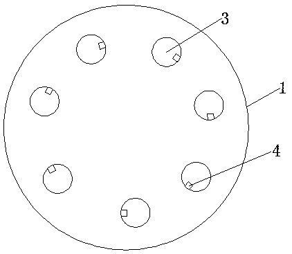
[0019] The invention provides a fast cutting device for hard alloy round rods. The fast cutting device for hard alloy round rods includes: a tooling platform 1, a receiving platform 2 and a transmission device; wherein, the tooling platform 1 is provided with multiple A working hole 3, the plurality of working holes 3 are equidistantly spaced to form a circle, and each working hole 3 is provided with a telescopic die block 4 for engaging an alloy round bar; the upper end of the tooling platform 1 is provided with an inverted A rotary motor...


PUM


Abstract

The invention provides a quick cutting device for a cemented carbide round rod. The quick cutting device for the cemented carbide round rod comprises a tooling platform, a bearing platform and a conveying device; a plurality of working holes are formed in the tooling platform, the multiple working holes are surrounded into a circle at equal intervals, and telescopic die blocks are correspondinglyarranged in the working holes; a rotary motor is arranged at the upper end of the tooling platform, a laser cutting machine is installed on the output shaft of the rotary motor in a sleeving mode, andwedge-shaped blocks used for pulling telescopic dies are arranged on the upper part of the output shaft; a plurality of leakage holes corresponding to the working holes one by one are circumferentially formed in the bearing platform, baffle plates are correspondingly and rotatably connected to one sides of the bottom ends of the leakage holes, and telescopic baffle blocks used for pulling the baffle plates are arranged at the lower end of the output shaft; and the quick cutting device further comprises a measuring column for supporting two sides of the tooling platform, a scale is arranged onthe measuring column, and the bearing platform is slidably installed on the measuring column in a sleeving mode. Through the rotation of the laser cutting machine, an alloy round rod with a set length exposed below the multiple working holes is cut, and accurate and quick cutting is achieved.

Description

technical field [0001] The invention relates to the technical field of cutting alloy round rods, in particular to a fast cutting device for hard alloy round rods. Background technique [0002] After the hard alloy round rod is processed and formed, the rod should be cut according to the required size. At present, the cutting of alloy rods mainly adopts manual cutting. Due to the great influence of human factors on the size of the rods, the work efficiency is low and the yield rate is low; in the process of rapid development of today's technology, how to achieve high-speed and precise cutting of cemented carbide round rods And it has the process of automatic cutting to realize rapid production, which is an urgent problem to be solved. Contents of the invention [0003] The object of the present invention is to provide a fast cutting device for hard alloy round rods in order to overcome the deficiencies of the prior art. [0004] The present invention is realized through t...

Claims


Application Information

Patent Timeline
Patent Type & Authority Applications(China)
IPC IPC(8): B23K26/38B23K26/08B23K26/70
CPCB23K26/0876B23K26/38B23K37/047
Inventor 陈明
Owner ZHUZHOU JINGGONG CEMENTED CARBIDE
Learn More