
Heat treatment technology for heavy drill rod with diameter being larger than or equal to phi 175 mm

A drill rod and process technology, which is applied in the field of heat treatment of heavy drill rods, can solve the problems of poor wear resistance, difficulty for manufacturers to bear, and high process cost, and achieve the effect of ingenious heat treatment process, reducing the number of replacements and saving steel resources

Active Publication Date: 2020-07-10
江阴吉中特殊钢带有限公司
View PDF5 Cites 0 Cited by
  • Summary
  • Abstract
  • Description
  • Claims
  • Application Information

AI Technical Summary

Problems solved by technology

[0006] However, even so, the hardenability of steel is still limited, even if the hardening radius of brine quenching is ≤55mm, there is no problem in hardening small drill rods
However, there are difficulties in hardening heavy-duty drill rods. For this problem, the current practice of major manufacturers is to either use the purchased expensive quenching liquid (but it can only be improved, the hardening radius is still ≤75mm, and it is still not hardenable. Heavy-duty drill rods with a diameter ≥ φ195mm), the process cost is very high, which makes it difficult for manufacturers to bear; or the traditional process used in the production of small drill rods is still used. The wear resistance of the internal structure is very poor. In fact, it is the original pearlite structure formed during hot rolling. Therefore, when using this kind of drill rod, the wear rate of the drill rod is high, which is 5-6 times faster than that of all hardened drill rods. times, the long-term use cost is also higher

Method used


Image

  • Heat treatment technology for heavy drill rod with diameter being larger than or equal to phi 175 mm
  • Heat treatment technology for heavy drill rod with diameter being larger than or equal to phi 175 mm
  • Heat treatment technology for heavy drill rod with diameter being larger than or equal to phi 175 mm

Examples


Embodiment 1

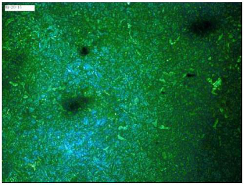
[0047] Such as figure 1 Shown is the sample HQ-20-15 under the 100°C boiling water quenching process of the present invention, using a φ195×300mm round steel to simulate a φ195mm drill rod, a 500-fold microscope photo of the center of the round steel, and the black spot in the lens is a microscope Please ignore the pollution. The sample HQ-20-15 shows that it is not perfect quenched sorbite. After testing, its hardness is HV440;

Embodiment 2

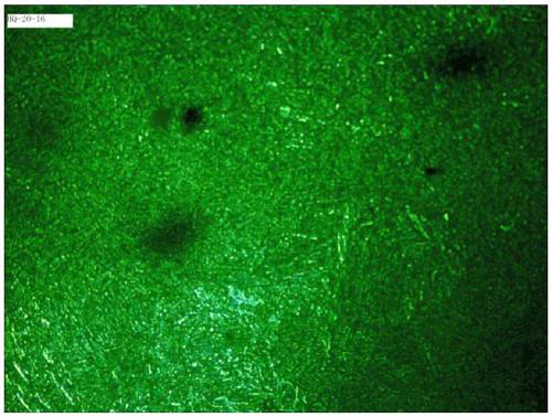
[0049] Such as figure 2 Shown is the sample HQ-20-16 under the 85-75 ℃ hot water quenching process of the present invention, using φ195×300mm round steel to simulate the 500 times microscopic structure photo of the round steel core after the φ195mm drill rod, the black in the lens Spots are microscopic contamination, please ignore. The sample HQ-20-16 shows a more perfect quenched sorbite. After testing, its hardness is HV498.


PUM

PropertyMeasurementUnit
diameteraaaaaaaaaa
diameteraaaaaaaaaa
diameteraaaaaaaaaa

Abstract

The invention discloses a heat treatment technology for a heavy drill rod with the diameter being larger than or equal to phi 175 mm. The heat treatment technology comprises the following steps that (1) the drill rod is heated and austenitized; (2) the drill rod processed through the step (1) is immersed into hot water at the temperature of 75-100 DEG C for quenching, and the drill rod is taken out after being integrally and directly quenched to form a quenched sorbite structure; and (3) the drill rod obtained in the step (2) is cooled to obtain a final finished product. The heat treatment technology is ingenious, the heavy drill rod is quenched into the quenched finished product through a hot water quenching mode, the production efficiency is very high, the cost is only 50% of that of common quenching and tempering heat treatment, and the whole technology is more environmentally friendly; the service life of the obtained heavy drill rod is prolonged by 75% or above compared with thatof an existing heavy drill rod subjected to quenching and tempering heat treatment, the use cost of the drill rod is reduced, in addition, steel resources are saved, and especially, under the condition that heavy drill rods are nearly increased exponentially every year, economic benefits and environmental benefits are great.

Description

technical field [0001] The invention belongs to the field of heat treatment, and in particular relates to a heat treatment process for a heavy-duty drill rod with a diameter ≥ φ175mm by quenching a heavy-duty drill rod with hot water at 75-100°C into a quenched sorbite structure. Background technique [0002] With the increasing volume of rock drilling projects such as mining, tunnel excavation, water conservancy projects and urban infrastructure, the demand for heavy-duty drill rods has grown exponentially (more than tenfold from 2017 to 2019). Heavy-duty drill rods mainly refer to drill rods with a diameter ≥ φ195mm. The steel type is 42CrMo. The production process is first forged, turned and formed, and then quenched and tempered. [0003] The purpose of adjusting the heat treatment is that according to the environmental conditions of the heavy-duty drill rod, the drill rod is required: 1). The overall ability to absorb impact energy is strong, and the core of the drill r...

Claims


Application Information

Patent Timeline
Patent Type & Authority Applications(China)
IPC IPC(8): C21D9/00C21D1/18
CPCC21D9/0075C21D1/18C21D2211/009Y02P10/20
Inventor 顾建中顾婷婷
Owner 江阴吉中特殊钢带有限公司
Learn More