Automatic regulating device for water injection flow

An automatic adjustment and flow rate technology, applied in the direction of valve device, valve operation/release device, valve details, etc., can solve the problems of inaccurate oil injection volume, increased driving pressure, low crude oil temperature, etc., and reduce manual adjustment Not in time, improve the transmission efficiency, the effect of low temperature

Inactive Publication Date: 2020-07-10
刘超
View PDF8 Cites 1 Cited by
  • Summary
  • Abstract
  • Description
  • Claims
  • Application Information

AI Technical Summary

Problems solved by technology

[0004] The device is designed based on the principle that the temperature and pressure of crude oil fluid are inversely proportional. The temperature of crude oil is low, the viscosity is high, and the driving pressure increases. However, the pressure of crude oil connected to the device is only the pressure at the rear of the valve core. Hot water has not been blended, that is, the temperature and pressure of crude oil have not changed due to the addition of hot water. Using this pressure control to adjust the water flow rate cannot accurately adjust the injection volume of hot water at different temperatures according to the viscosity of oil. the goal of

Method used


Image

  • Automatic regulating device for water injection flow

Examples


Embodiment Construction

[0014] The present invention will be further explained below in conjunction with the drawings:

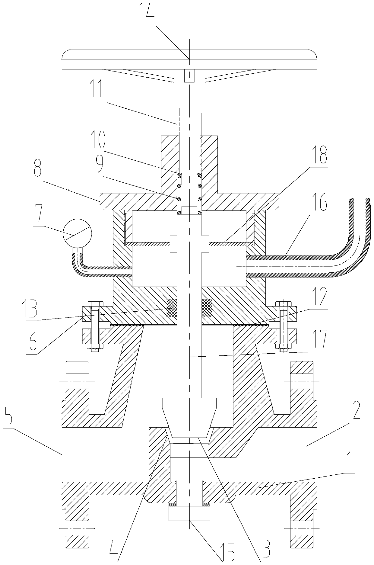
[0015] by figure 1 As shown, an automatic adjustment device for water injection flow includes a lower valve body 1. The lower valve body 1 is divided into an inlet cavity 5 and an outlet cavity 2. A tapered hole 4 is connected between the inlet cavity 5 and the outlet cavity 2. The tapered hole 4 is a structure with a large upper hole and a small lower hole. The conical surface between the tapered hole 4 and the valve core 3 is matched and the conical surface between the tapered hole 4 and the valve core 3 is matched. When the valve core 3 is pressed against the tapered hole The conical surface of 4 produces a sealing effect. Under a certain pressure, the size of the gap between the conical annular surface of the valve core 3 and the conical annular surface of the tapered hole 4 determines the liquid flow through the annular space;

[0016] The upper flange of the lower valve body 1 is...


PUM


Abstract

The invention provides an automatic regulating device for water injection flow, and relates to the technical field of oil and gas gathering and transportation. A diaphragm is clamped between the bottom of an upper valve body connected to a valve cover and the upper valve body, the diaphragm is connected with a nut, the nut is in threaded connection with the upper thread of a valve rod, the lower part of the valve rod is fixedly connected with a valve core, and a back pressure connecting pipe is arranged in an inner cavity of the upper valve body at the lower part of the diaphragm and communicates with the inner cavity of the upper valve body at the lower part of the diaphragm. The automatic regulating device has the following beneficial effects that the device is designed by utilizing theprinciple that the temperature and the pressure of the crude oil fluid are in inverse ratio, the temperature of the crude oil is low, the viscosity is large, the driving pressure is increased, and theback pressure connecting pipe connected to a crude oil pipeline is adopted to drive the valve rod to rise and fall under the diaphragm to automatically adjust the water mixing flow; and moreover, theflow can be adjusted as required, manual operation is not needed, the water mixing flow is accurate, the energy consumption loss caused by the fact that manual adjustment is not timely and accurate is reduced, and the crude oil conveying efficiency is improved.

Description

Technical field: [0001] The invention relates to the technical field of oil and gas gathering and transportation, in particular to a water injection flow automatic adjustment device. Background technique: [0002] Petroleum is a liquid whose viscosity changes with temperature. The freezing point of crude oil is generally 20-38 degrees Celsius. The lower the temperature, the higher the viscosity of oil, which makes pipeline transportation difficult. At present, in response to this problem in oil fields, heat is generally injected into the oil. Water, in order to save costs, the temperature at the end of the pipeline transportation is 5 degrees Celsius higher than the freezing point of the crude oil. However, how high temperature water and how much water should be injected still depends on manual adjustment, and the viscosity coefficient of oil varies, so , The manual adjustment is obviously not accurate enough. It is particularly important to invent a device that can automatically...

Claims


Application Information

Patent Timeline
Patent Type & Authority Applications(China)
IPC IPC(8): F16K17/06F16K17/20F16K31/126F16K37/00
CPCF16K17/0486F16K17/06F16K17/20F16K31/126F16K37/0091
Inventor 刘超
Owner 刘超
Why Eureka
Try Eureka