Pressuring, catalyzing and purifying treatment device for efficient combustion waste gas heat energy recycling

A technology for heat energy recovery and combustion of waste gas, applied in lighting and heating equipment, combustion methods, combustion types, etc., can solve the problems of waste, natural dissipation of heat energy without utilization, effect impact, etc., to improve recycling rate and waste gas treatment. effect of effect

Inactive Publication Date: 2020-07-10
新昌县羽林街道全利机械厂
View PDF0 Cites 2 Cited by
  • Summary
  • Abstract
  • Description
  • Claims
  • Application Information

AI Technical Summary

Problems solved by technology

[0007] The purpose of the present invention is to provide a pressurized catalytic purification treatment equipment for efficient combustion waste gas heat energy recovery, to solve the above background technology that the combustion waste gas contains a large amount of heat energy, the heat energy gradually dissipates in the process of purification treatment, and the heat energy is not added. It is wasteful to use natural dissipation, and some existing purification treatment devices are not convenient for splitting and refining treatment during use. When the exhaust gas reaches a saturated state on the surface of the adsorbate inside the purification device, the effect of treating exhaust gas inside the device will be affected.

Method used


Image

  • Pressuring, catalyzing and purifying treatment device for efficient combustion waste gas heat energy recycling
  • Pressuring, catalyzing and purifying treatment device for efficient combustion waste gas heat energy recycling
  • Pressuring, catalyzing and purifying treatment device for efficient combustion waste gas heat energy recycling

Examples


Embodiment Construction

[0026] The following will clearly and completely describe the technical solutions in the embodiments of the present invention with reference to the accompanying drawings in the embodiments of the present invention. Obviously, the described embodiments are only some, not all, embodiments of the present invention. Based on the embodiments of the present invention, all other embodiments obtained by persons of ordinary skill in the art without making creative efforts belong to the protection scope of the present invention.

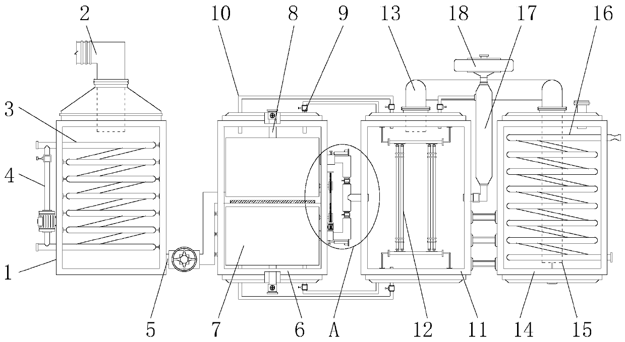
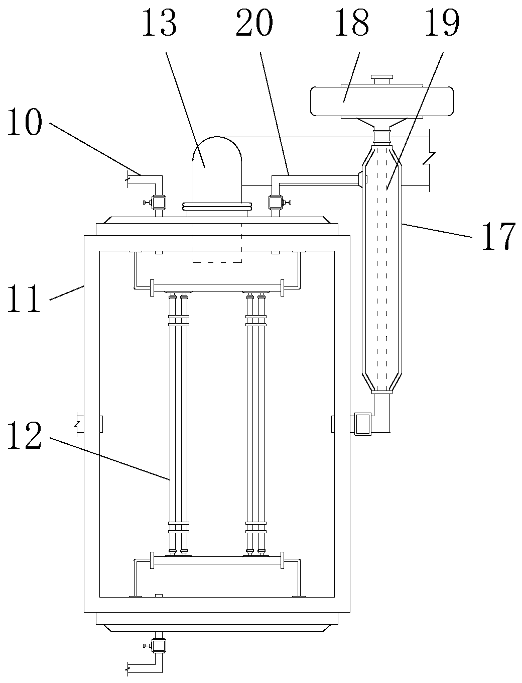
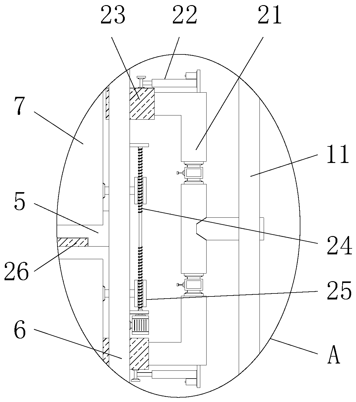
[0027] see Figure 1-6 , the present invention provides a technical solution: a pressurized catalytic purification treatment equipment for high-efficiency combustion waste gas heat energy recovery, including a cooling tank 1, an intake pipe 2, a left curved pipe 3, a negative pressure pipe 4, a connecting pipe 5, Compression adsorption tank 6, built-in tank 7, exhaust pipe 8, air outlet pipe 9, heat preservation pipe 10, heating tank 11, high temperature heati...


PUM


Abstract

The invention discloses a pressuring, catalyzing and purifying treatment device for efficient combustion waste gas heat energy recycling. The pressuring, catalyzing and purifying treatment device forefficient combustion waste gas heat energy recycling comprises a cooling tank, a gas exhaust pipe and a base plate. The upper surface of the cooling tank is connected with a gas intake pipe in a penetrated manner. The cooling tank is connected with a compression adsorption tank through a connection pipe. The gas exhaust pipe is connected to the side face of the compression adsorption tank in a penetrated manner. A preheating pipe is fixedly installed on the outer portion of the right side of the heating tank. The outer side face of the compression adsorption tank is connected with the heatingtank through a flow distributing pipe. The outer portion of the right side of the compression adsorption tank is rotationally connected with a lead screw. The inner portion of the side face of the connection pipe is movably connected with a seal plate. A fixing rod is welded to the middle of the inner portion of the connection pipe. The pressuring, catalyzing and purifying treatment device for efficient combustion waste gas heat energy recycling adopts a novel structural design, so that the pressuring, catalyzing and purifying treatment device can recycle and utilize heat energy in waste gas during machining; and the pressuring, catalyzing and purifying treatment device is internally provided with the flow distributing treatment structure, so that the waste gas treatment effect is improved.

Description

technical field [0001] The invention relates to the technical field of combustion waste gas heat energy recovery, in particular to a pressurized catalytic purification treatment device for high-efficiency combustion waste gas heat energy recovery. Background technique [0002] The industrial combustion exhaust gas produced by processing contains large particles of dust, and direct emission of processing will cause great pollution. Industrial processing exhaust gas discharges a large amount, and it is necessary to use a purification treatment device to filter the exhaust gas and reduce environmental pollution. Currently, industrial waste gas There are many treatment methods, some of which use catalyst pressurized mixing to decompose harmful substances in the exhaust gas, so as to achieve the purpose of exhaust gas treatment. [0003] With the continuous processing and use of the purification treatment device, the following problems were found in the process of use: [0004] ...

Claims


Application Information

Patent Timeline
Patent Type & Authority Applications(China)
IPC IPC(8): F23G7/07F23G5/14F23G5/44F23G5/46F23J15/02F23J15/06
CPCF23G5/14F23G5/44F23G5/46F23G7/07F23J15/025F23J15/06Y02E20/30
Inventor 蒋家慧
Owner 新昌县羽林街道全利机械厂
Why Eureka
Try Eureka