Automatic production line for connector terminals, and process thereof

An automatic production line and connector terminal technology, applied in connection, contact manufacturing, circuit/collector components, etc., can solve the problems of low welding efficiency and high labor cost, and achieve small operating space, precise welding, and large operating range Effect

Active Publication Date: 2020-07-10
浙江新力达电力金具有限公司
View PDF6 Cites 1 Cited by
  • Summary
  • Abstract
  • Description
  • Claims
  • Application Information

AI Technical Summary

Problems solved by technology

[0003] The purpose of the present invention is to provide an automatic production line for connector te

Method used


Image

  • Automatic production line for connector terminals, and process thereof
  • Automatic production line for connector terminals, and process thereof
  • Automatic production line for connector terminals, and process thereof

Examples


Embodiment 1

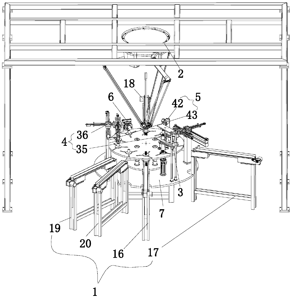
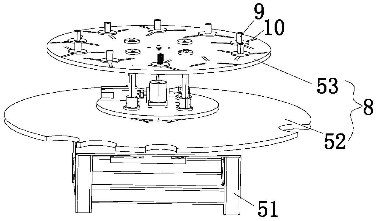
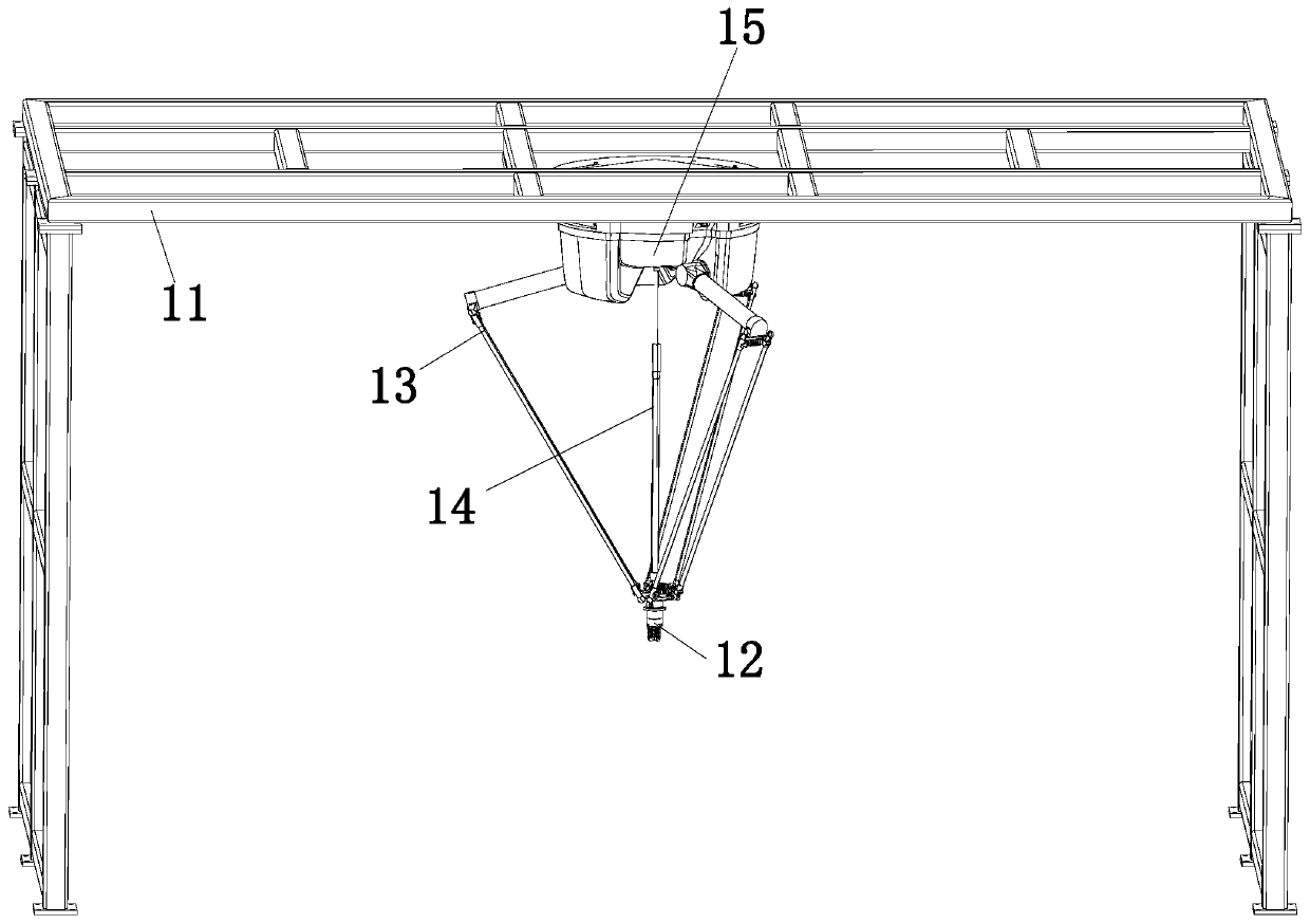
[0038] Combine below Figure 1 to Figure 11 As shown, the embodiment of the present invention provides an automatic production line for connector terminals, including a narrow conveyor belt 1, a spider manipulator 2, a twisting mechanism 3, a welding mechanism 4, a detection mechanism 5, a turning mechanism 6, and a platform 7. The platform 7 is designed In the middle of the whole equipment, the narrow-distance conveyor belt 1 is arranged around the platform 7, and the spider-man manipulator 2 is arranged on the upper part of the platform 7 and the spider-man manipulator 2 can be placed on the narrow-distance conveyer belt 1, the twist-and-pull mechanism 3. Working on the welding mechanism 4, the detection mechanism 5, the turning mechanism 6 and the platform 7, the twisting and pulling mechanism 3, the welding mechanism 4, and the turning mechanism 6 are successively arranged at the fixed position on the upper edge of the platform 7, each The structures are coordinated with e...

Embodiment 2

[0054] The connector automatic production line described in embodiment 1 comprises the following steps:

[0055] In the first step, the elastic grid is firmly placed on the tooling 9 at the corresponding position through the mechanical claw 12, and the movable plate 53 starts to rotate counterclockwise;

[0056] In the second step, when the elastic grid reaches the twist-pull mechanism 3, first start the lower cylinder 21 to stretch out the output end, release the grasping finger 57, place the elastic grid and tooling 9 on the grasping palm 58, and contract the lower cylinder 21, clamp the lower end of the elastic grid, and then start the electric cylinder 22, the output end of the electric cylinder 22 descends to drive the twist-pull cover 26, and the twist-pull cover 26 covers the elastic grid, and starts the thumb Cylinder 25, the output shaft 54 ​​drives the fixed claw 55 to move inwardly under the action of the thumb cylinder 25, the fixed claw 55 clamps the upper end of ...


PUM


Abstract

The invention discloses an automatic production line for connector terminals. The invention belongs to the technical field of connectors, the automatic production line comprises a narrow-distance conveying belt, a spider man manipulator, a twisting and pulling mechanism, a welding mechanism, a detection mechanism, a turnover mechanism and a platform, the narrow-distance conveying belt is arrangedon the periphery of the platform. The spider man manipulator is arranged on the upper portion of the platform and can work on the narrow-distance conveying belt, the twisting and pulling mechanism, the welding mechanism, the detection mechanism, the turnover mechanism and the platform. The twisting and pulling mechanism, the welding mechanism and the overturning mechanism are sequentially arrangedat the fixed position of the upper edge of the lifting type rotary disc. All the structures are matched and connected in sequence, so that all procedures in the whole production can be integrated ina more matched mode, a complete assembly line is formed, the space is saved, operation is convenient, meanwhile, the production efficiency is greatly improved, and the labor cost is saved.

Description

technical field [0001] The invention relates to the technical field of connectors, in particular to an automatic production line for connecting connector terminals and a process thereof. Background technique [0002] At present, in-line electrical connectors are set in the connectors for better conduction. A sleeve-type laser welding connector terminal with a publication number of CN202474316U includes a sleeve and an elastic grid built in the sleeve. , the two ends of the elastic grid are provided with welding ends, and the elastic grid is correspondingly welded in the sleeve through the welding ends. The utility model builds an elastic grid in the sleeve. The elastic grid is a mesh elastic radial cylindrical inner grid. The elastic contact of the male pin, and this kind of connector terminal needs to weld the sleeve and the elastic grid. Usually, one-sided automatic welding can be realized, but the shape of the elastic grid cannot be changed, so a separate machine or a se...

Claims


Application Information

Patent Timeline
IPC IPC(8): H01R43/16H01R43/02H01R43/00B07C5/34
CPCB07C5/34B07C2501/0063H01R43/00H01R43/02H01R43/16
Inventor 何凤凤
Owner 浙江新力达电力金具有限公司
Why Eureka
Try Eureka