Concentrated winding transverse flux permanent magnet synchronous motor

A technology of permanent magnet synchronous motor and transverse magnetic flux, which is applied to synchronous machines, synchronous motors with stationary armatures and rotating magnets, windings, etc., which can solve the problems of copper loss and only function as a connection, and improve utilization Ratio, improvement of winding utilization, and improvement of cogging torque

Active Publication Date: 2020-07-10
HUAZHONG UNIV OF SCI & TECH
View PDF13 Cites 9 Cited by
  • Summary
  • Abstract
  • Description
  • Claims
  • Application Information

AI Technical Summary

Problems solved by technology

Compared with the end winding of the traditional radial flux motor, which occupies the axial length without outputting torque, the traditional transverse flux motor has no end winding at both ends of the stator, thereby shortening the axial length, but the gap between the teeth The connected windings also produce copper losses without doing work
The stator windings of these two motors have parts that do not do work but produce copper loss and only serve as a connection. How to improve or even overcome this shortcoming, so as to improve the utilization rate of the stator windings, there is still no solution

Method used


Image

  • Concentrated winding transverse flux permanent magnet synchronous motor
  • Concentrated winding transverse flux permanent magnet synchronous motor
  • Concentrated winding transverse flux permanent magnet synchronous motor

Examples


Embodiment 1

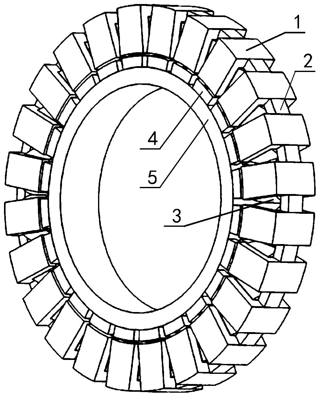
[0029] figure 1 It is a three-dimensional schematic diagram of a single-phase motor with concentrated winding transverse flux permanent magnet synchronous motor in this embodiment, including a stator part and a rotor part, and the stator part includes a stator "E" tooth 1, a stator yoke part 2 and a stator winding 3 , the rotor part includes the rotor magnetic steel 4 and the rotor yoke 5, and there is an air gap between the stator and the rotor. In this embodiment, the number of pole pairs P 1 12, the number of stator teeth is 2P 1 24, number of coils 2P 1 for 24.

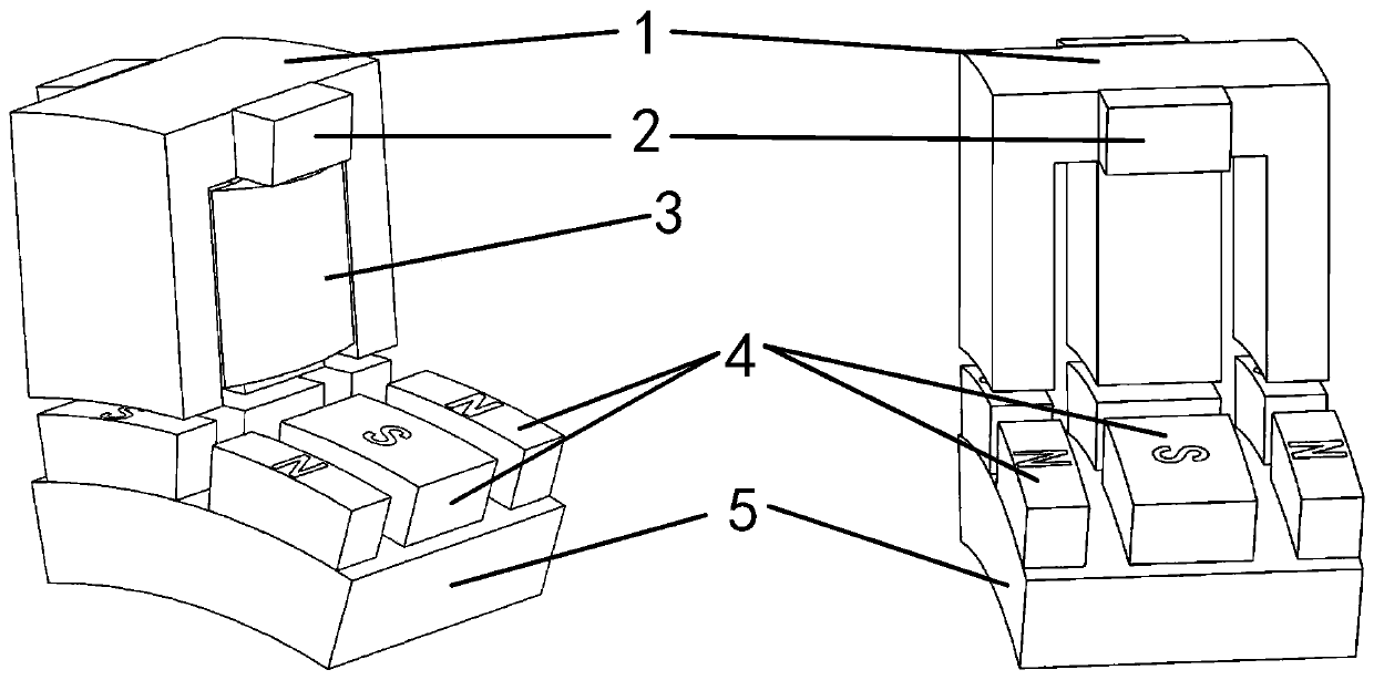
[0030] figure 2 It is a partially enlarged schematic diagram of a single-phase motor with concentrated winding transverse flux permanent magnet synchronous motor in this embodiment. The left and right diagrams are from different perspectives and the stator winding 3 is hidden in the right diagram. In the figure, the stator "E" tooth 1 and the stator yoke 2 only show one pole (that is, the 1 / 24 stator core mo...

Embodiment 2

[0039] Figure 5 It is a three-dimensional structural schematic diagram of a concentrated winding transverse flux permanent magnet synchronous motor in this embodiment. The three-phase motor is composed of three identical single-phase motors connected in series axially. Each phase motor includes stator "E" tooth 1, stator yoke 2, stator winding 3, rotor magnetic steel 4 and rotor yoke 5, A-phase motor 10, B-phase motor 11, and C-phase motor 12 are identical, three The phases are connected in series in the axial direction, and the stator parts are staggered by 120° in the same direction.

[0040] Figure 6 It is a three-dimensional schematic diagram of the stator winding of a three-phase motor with concentrated winding transverse flux permanent magnet synchronous motor in this embodiment, and the A-phase winding 13, B-phase winding 14, and C-phase winding 15 are sequentially staggered by 120°.

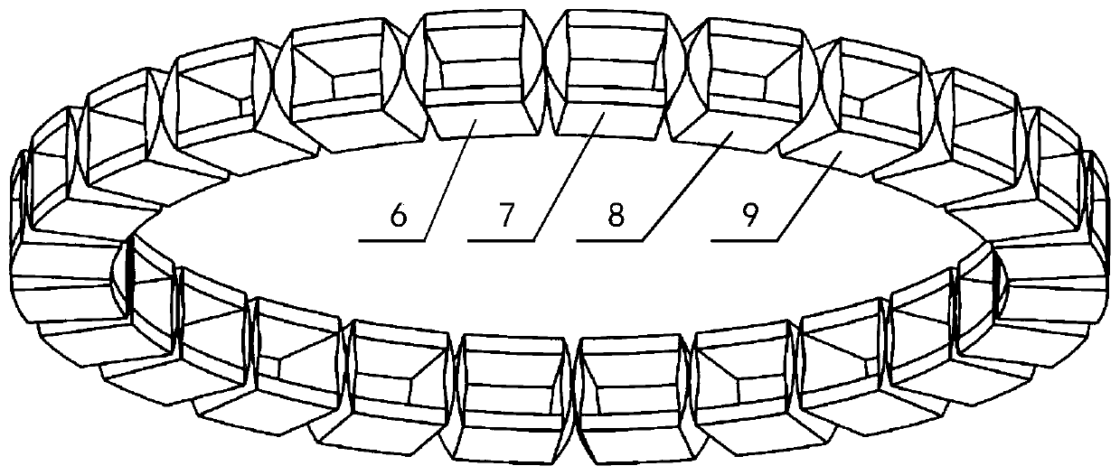
[0041] Figure 7 It is a three-dimensional structural schematic diagram of the r...

Embodiment 3

[0044] Figure 8 It is a schematic diagram of a single-phase motor explosion of a concentrated winding transverse flux permanent magnet synchronous motor in this embodiment. In the actual assembly process, the stator "E" type teeth 1 can be divided into "C" type iron core teeth 19 and intermediate teeth The two parts of 21, the stator yoke 20 and the middle tooth 21 can be realized by axial lamination, and at the same time, the "C" type iron core teeth 19 can be fixed, which solves the problem that the stator teeth of the traditional transverse flux motor are separated from each other and are not easy to fix . In this implementation manner, the "C"-shaped iron core teeth 19 can also be realized by "C"-shaped laminations arranged in the circumferential direction, which avoids the use of a special soft magnetic composite material core and has more practical value. The stator winding 22 and the rotor magnetic steel 23 have not changed. In order to avoid the excessive iron loss o...


PUM


Abstract

The invention discloses a concentrated winding transverse flux permanent magnet synchronous motor, which comprises stator E-shaped teeth, a stator yoke part, a stator winding, rotor magnetic steel anda rotor yoke part, the stator E-shaped teeth comprise three teeth and two grooves, and the three teeth face the air gap and are axially arranged; the stator winding is wound on the middle teeth of the stator E-shaped teeth and fills the two grooves to form a concentrated winding coil, and the winding directions of the coils of the two adjacent stator E-shaped teeth are opposite; the stator yoke part wraps the exposed windings of the two adjacent stator E-shaped teeth; each pole of rotor magnetic steel is formed by axially arranging three pieces of magnetic steel with alternate N poles and S poles, and the three pieces of magnetic steel are respectively aligned with three teeth of the E-shaped teeth of the stator; the polarities of the rotor magnetic steels of two adjacent poles are opposite; the rotor yoke part provides a magnetic flux loop and comprises a radial magnetic flux direction and a transverse magnetic flux direction. According to the invention, the utilization rate of the stator winding can be greatly improved.

Description

technical field [0001] The invention belongs to the technical field of permanent magnet motors, and more specifically relates to a permanent magnet synchronous motor with concentrated winding transverse flux. Background technique [0002] Since the Industrial Revolution, human society has entered the electrical age from the steam age. Machine production has gradually replaced human labor. Form motors are the most widely used electrical equipment in industrial and agricultural production and civil industries. The annual electricity consumption of various motors accounts for about 70% of my country's total power generation. Various new energy sources such as photovoltaics, wind power, and nuclear power also use electric energy as a secondary energy source, so higher requirements are placed on the development of motors. [0003] my country's economy is huge, and under the background of the energy crisis gradually restricting economic development, power shortage will be the norm...

Claims


Application Information

Patent Timeline
Patent Type & Authority Applications(China)
IPC IPC(8): H02K1/14H02K1/27H02K1/18H02K1/16H02K3/28H02K3/12H02K3/18H02K3/487H02K3/50H02K21/12
CPCH02K1/146H02K1/165H02K1/18H02K1/2766H02K1/2786H02K3/12H02K3/18H02K3/28H02K3/487H02K3/50H02K21/125H02K2201/03H02K2201/12H02K2213/03
Inventor 李亮李大伟曲荣海
Owner HUAZHONG UNIV OF SCI & TECH
Why Eureka
Try Eureka